Suzuki Grand Vitara JB627. Manual — part 104
1F-10 Engine Cooling System:
Water Pump Removal and Installation
S6JB0B1606014
Removal
1) Remove engine assembly from vehicle referring to
“Engine Assembly Removal and Installation in
Section 1D”.
2) Remove timing chain cover referring to “Timing
Chain Cover Removal and Installation in Section
1D”.
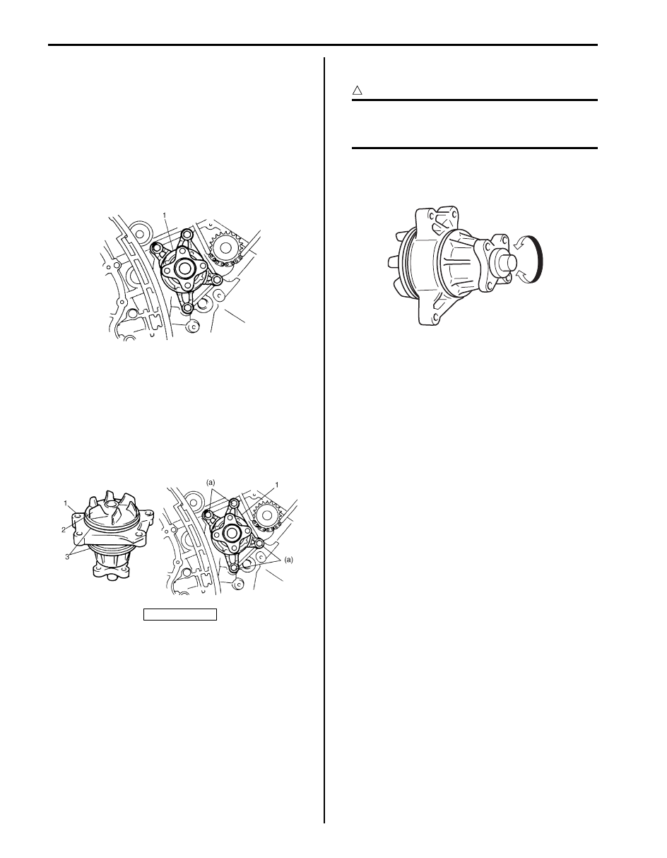
3) Remove water pump assembly (1) from cylinder
block.
Installation
1) Install new O-rings (3) to water pump (1).
2) Install water pump to cylinder block. Tighten water
pump bolts to specified torque.
Tightening torque
Water pump bolt (a): 25 N·m (2.5 kgf-m, 18.0 lb-
ft)
3) Install timing chain cover referring to “Timing Chain
Cover Removal and Installation in Section 1D”.
4) Install engine assembly to vehicle referring to
“Engine Assembly Removal and Installation in
Section 1D”.
Water Pump Inspection
S6JB0B1606015
CAUTION
!
Do not disassemble water pump.
If any repair is required on pump, replace it
as assembly.
Rotate water pump by hand to check for smooth
operation. If pump does not rotate smoothly or makes
abnormal noise, replace it.
2. Impeller
I6JB01160012-01
I6JB01160013-01
I6JB01160014-01
Engine Cooling System: 1F-11
Specifications
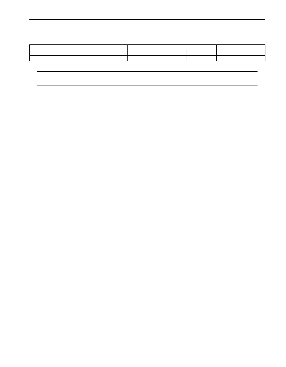
Tightening Torque Specifications
S6JB0B1607001
NOTE
The specified tightening torque is also described in the following.
“Cooling System Components”
Reference:
For the tightening torque of fastener not specified in this section, refer to “Fastener Information in Section 0A”.
Fastening part
Tightening torque
Note
N
⋅m
kgf-m
lb-ft
Water pump bolt
25
2.5
18.0

1G-1 Fuel System:
Engine
Fuel System
Precautions
Precautions on Fuel System Service
S6JB0B1700001
WARNING
!
Before attempting service of any type on fuel system, the following should be always observed in
order to reduce the risk or fire and personal injury.
• Disconnect negative (–) cable at battery.
• Do not smoke, and place no smoking signs near work area.
• Be sure to have CO
2
fire extinguisher handy.
• Be sure to perform work in a well-ventilated area and away from any open flames (such as gas hot
heater).
• Wear safety glasses.
• To relieve fuel vapor pressure in fuel tank, remove fuel filler cap from fuel filler neck and then
reinstall it.
• As fuel feed line is still under high fuel pressure even after stopping engine, loosening or
disconnecting fuel feed line directly may cause dangerous spout of fuel. Before loosening or
disconnecting fuel feed line, make sure to relieve fuel pressure referring to “Fuel Pressure Relief
Procedure”.
• A small amount of fuel may be released when the fuel line is disconnected. In order to reduce the
risk of personal injury, cover a shop cloth to the fitting to be disconnected. Be sure to put that cloth
in an approved container after disconnecting.
• Never run engine with fuel pump relay disconnected when engine and exhaust system are hot.
• Note that fuel hose connection varies with each type of pipe. Be sure to connect and clamp each
hose correctly referring to “Fuel Hose Disconnecting and Reconnecting”.
After connecting, make sure that it has no twist or kink.
• When installing injector or fuel feed pipe, lubricate its O-ring with gasoline.
General Description
Fuel System Description
S6JB0B1701001
CAUTION
!
This engine requires the unleaded fuel only.
The leaded and/or low lead fuel can result in
engine damage and reduce the effectiveness
of the emission control system.
The main components of the fuel system are fuel tank,
fuel pump assembly (with fuel filter and fuel level gauge),
fuel pressure regulator, fuel feed line, fuel return line and
fuel vapor line.
For the details of fuel flow, refer to “Fuel Delivery System
Diagram”.
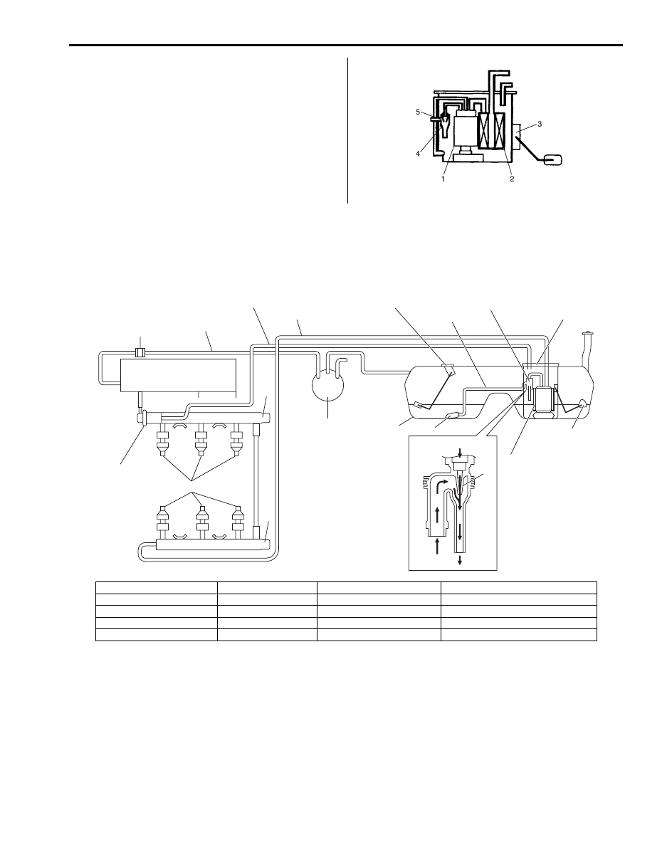
Fuel Delivery System Description
S6JB0B1701002
The fuel delivery system consists of the fuel tank, fuel
pump assembly (with built-in fuel filter), fuel pressure
regulator, delivery pipe, injectors, fuel return line, fuel
vapor line and fuel feed line.
The fuel in the fuel tank is pumped up by the fuel pump,
sent into delivery pipe and injected by the injectors.
As the fuel pump assembly is equipped with built-in fuel
filter, the fuel is filtered and its pressure is regulated after
being sent to the feed pipe.
The excess fuel at fuel pressure regulation process is
returned back into the fuel tank.
Also, fuel vapor generated in fuel tank is led through the
fuel vapor line into the EVAP canister.
For system diagram, refer to “Fuel Delivery System
Diagram”.
Fuel System: 1G-2
Fuel Pump Description
S6JB0B1701003
The fuel pump (1) is an in-tank type electric pump.
Incorporated in the pump assembly are;
a fuel filter (2) included and a fuel level gauge (3)
attached.
Also, the jet pump (4) installed in the fuel pump sucks up
the fuel from the sub fuel level sensor side to main fuel
level sensor side through the fuel suction pipe / hose by
using the negative pressure produced when the part of
pressurised fuel with the fuel pump passes the venturi
(5).
Schematic and Routing Diagram
Fuel Delivery System Diagram
S6JB0B1702001
I5JB0A171001-03
20
7
10
6
9
13
15
14
2
12
11
19
17
18
16
1
4
4
5
3
8
I6JB01170001-01
1. Fuel tank
6. Fuel feed line
11. Fuel filter
16. Fuel suction filter
2. Fuel pump
7. Fuel vapor line
12. Main fuel level sensor
17. Pressurised fuel from fuel pump
3. Fuel pressure regulator
8. Intake manifold
13. Sub fuel level sensor
18. Fuel feeded from fuel suction hose
4. Delivery pipe
9. EVAP canister
14. Jet pump
19. Venturi
5. Fuel injector
10. Fuel return line
15. Fuel suction pipe / hose
20. EVAP canister purge valve
Нет комментариевНе стесняйтесь поделиться с нами вашим ценным мнением.
Текст