Suzuki Grand Vitara JB627. Manual — part 44
1A-125 Engine General Information and Diagnosis:
DTC P0403: Exhaust Gas Recirculation Control Circuit
S6JB0B1104044
Wiring Diagram
Refer to “DTC P0401 / P0402: Exhaust Gas Recirculation Flow Insufficient Detected / Excessive Detected”.
DTC Detecting Condition and Trouble Area
DTC Confirmation Procedure
WARNING
!
• When performing a road test, select a place where there is no traffic or possibility of a traffic
accident and be very careful during testing to avoid occurrence of an accident.
• Road test should be carried out with 2 persons, a driver and a tester, on a level road.
1) With ignition switch OFF, connect scan tool to DLC.
2) Turn ON ignition switch and clear DTC using scan tool.
3) Start engine and warm it up to normal operating temperature.
4) Run engine at 2000 rpm and increase engine speed to 5000 rpm and then decrease it to 2000 rpm noting in order
not to close throttle valve.
5) Repeat step 4) 4 times.
6) Stop vehicle and check DTC and pending DTC.
6
EGR valve check
1) Check EGR valve referring to “PCV Valve Inspection in
Is check result satisfactory?
Go to Step 7.
Faulty EGR valve.
7
MAP sensor check
1) Check MAP sensor for performance referring to
“Manifold Absolute Pressure (MAP) Sensor Inspection in
Section 1C”.
Is check result satisfactory?
EGR passage clogged.
If OK, substitute a
known good ECM and
recheck.
Replace MAP sensor.
Step
Action
Yes
No
DTC detecting condition
Trouble area
EGR valve control duty pulse monitor signal is less than 0.8 V at OFF duty
pulse or more than 2.2 V at ON duty pulse for more than 4 times.
(1 driving cycle detection logic)
• EGR valve circuit open
• EGR valve
• ECM

Engine General Information and Diagnosis: 1A-126
DTC Troubleshooting
Step
Action
Yes
No
1
Was “Engine and Emission Control System Check”
performed?
Go to Step 2.
Go to “Engine and
Emission Control
System Check”.
2
EGR valve power supply circuit check
1) With ignition switch OFF, disconnect connector from
EGR valve.
2) With ignition switch ON, check that EGR valve power
supply circuit voltage between.
• “a” terminal of EGR valve connector and vehicle body
ground is battery voltage.
• “b” terminal of EGR valve connector and vehicle body
ground is battery voltage.
Is it in good condition?
Go to Step 3.
EGR valve power
supply circuit is open or
shorted to ground.
3
Wiring harness check
1) Disconnect connectors from ECM with ignition switch
turned OFF.
2) Check for proper terminal connection to EGR valve and
ECM connectors.
3) If connections are OK, check that EGR valve control
circuit is as follows.
• Wiring harness resistance of all EGR valve control
circuits are less than 3
Ω.
• Insulation resistance between all EGR valve control
circuits and vehicle body ground are infinity.
Are they in good condition?
Go to Step 4.
Repair or replace
defective wire harness.
4
EGR valve check
1) Check EGR valve for resistance referring to “EGR Valve
Assembly Inspection (If Equipped) in Section 1B”.
Is it in good condition?
Substitute a known
good ECM and recheck.
Replace EGR valve.
I4JA01111012-01
1A-127 Engine General Information and Diagnosis:
DTC P0420 / P0430: Catalyst System Efficiency Below Threshold (Bank-1 / -2)
S6JB0B1104045
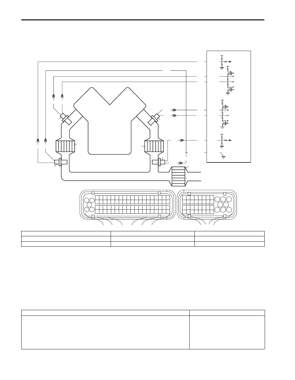
System / Wiring Diagram
System Description
ECM monitors oxygen concentration in the exhaust gas which has passed the warm up three way catalytic converter
by HO2S. When the catalyst is functioning properly, the variation cycle of HO2S output voltage (oxygen concentration)
is slower than that of A/F sensor output signal because the amount of oxygen in the exhaust gas is stored in warm up
three way catalytic converter.
A/F Sensor Description
Refer to “A/F Sensor Description”.
DTC Detecting Condition and Trouble Area
1
3 2
4
5
6
7
8
9
1110
12
13
14
15
16
17
18
19
20
17
18
19
20
21
22
23
24
25
26
27
28
29
30
31
33
34
35
36
37
38
39
40
32
1
2
3
4
5
6
7
8
9
10
11
12
13
14
15
16
21
22
23
24
25
26
27
28
29
30
31
32
33
34
35
36
37
38
39
40
41
42
43
44
45
46
47
48
49
50
51
52
53
54
55
56
57
58
59
60
61
62
63
64
65
66
67
68
69
70
71
72
73
74
75
76
77
78
79
80
81
E23
C37
C37-3
C37-67
C37-19
C37-18
C37-38
YEL
GRN
BRN
RED
WHT BLU
WHT
GRY/GRN
BLK
WHT
BLU
C37-37
C37-22
BLU
WHT
BLU
RED
GRN
WHT
Bank 2
Bank 1
5
1
4
2
6
7
3
8
I6JB01110039-02
1. Warm up TWC converter (Bank-2)
4. HO2S (Bank-2, Sensor-2)
7. HO2S (Bank-1, Sensor-2)
2. Warm up TWC converter (Bank-1)
5. A/F sensor (Bank-2, Sensor-1)
8. ECM
3. TWC converter
6. A/F sensor (Bank-1, Sensor-1)
DTC detecting condition
Trouble area
Correlation coefficient that is calculated on the basis of A/F sensor signal and
HO2S-2 signal exceeds specification when switched from RICH to LEAN in A/F
diagnostic frequency under prescribed running condition.
(2 driving cycle detection logic, monitoring once per driving cycle)
• WU-TWC converter
• Exhaust system
• A/F sensor
• HO2S-2
• ECM

Engine General Information and Diagnosis: 1A-128
DTC Confirmation Procedure
WARNING
!
• When performing a road test, select a place where there is no traffic or possibility of a traffic
accident and very careful during testing to avoid occurrence of an accident.
• Road test should be carried out with 2 persons, a driver and a tester, on a level road.
NOTE
Check to make sure that the following conditions are satisfied when using this “DTC Confirmation
Procedure”.
• Intake air temperature: between –14
°C and 70 °C (6.8 °F and 158 °F).
• Engine coolant temperature: higher than 58
°C (136 °F).
• The following DTCs are not detected: A/F sensor, A/F sensor heater, HO2S-2 and HO2S-2 heater.
1) With ignition switch OFF, connect scan tool.
2) Turn ON ignition switch and clear DTC by using scan tool if any.
3) Start engine and warm up to normal operating temperature.
4) Increase vehicle speed to 35 mph (56 km/h) or more.
5) Keep above vehicle speed for 5 min. (Throttle valve operating is kept constant in this step.)
6) Increase vehicle speed to 50 – 60 mph (80 – 100 km/h). (engine speed; 2500 – 3000 rpm)
7) Keep above vehicle speed for 5 min. (Throttle valve operating is kept constant in this step.)
8) Stop vehicle and check DTC and pending DTC by using scan tool.
DTC Troubleshooting
Step
Action
Yes
No
1
Was “Engine and Emission Control System Check”
performed?
Go to Step 2.
Go to “Engine and
Emission Control
System Check”.
2
Exhaust system visual inspection
1) Check exhaust system for leaks, damage and loose.
Is it in good condition?
Go to Step 3.
Repair or replace.
3
HO2S (bank-1 or bank-2) circuit check
1) Check signal and ground circuits of HO2-S (bank-1 or
bank-2) for high resistance referring to applicable step of
“DTC P0137 / P0138: O2 Sensor Circuit Low Voltage /
High Voltage (Sensor-2, Bank-1)” or “DTC P0157 /
P0158: O2 Sensor Circuit Low Voltage / High Voltage
(Sensor-2, Bank-2)”.
Are they in good condition?
Go to Step 4.
Repair or replace.
4
1) Replace exhaust manifold (built in warm up three way
catalytic converter) and exhaust center pipe (built in
three way catalytic converter).
2) Perform DTC confirmation procedure.
Is DTC P0420 (P0430) still detected?
Substitute a known
good ECM and recheck.
System is in good
condition.
Нет комментариевНе стесняйтесь поделиться с нами вашим ценным мнением.
Текст