Suzuki Grand Vitara JB627. Manual — part 289
7B-72 Air Conditioning System:
A/C Refrigerant Pressure Sensor and Its Circuit
Inspection
S6JB0B7206015
1) Disconnect A/C refrigerant pressure sensor
connector.
2) Turn ignition switch to ON position.
3) Check if voltage between “GRY/RED” wire terminal
and “GRY/GRN” wire terminal of A/C refrigerant
pressure sensor connector is 4.75 V to 5.25 V.
If not, check A/C refrigerant pressure sensor circuit.
4) Connect A/C refrigerant pressure sensor connector
with ignition switch turned OFF.
5) Connect manifold gauge set to the charging valves.
6) Check A/C refrigerant pressure sensor voltage of
ECM connector referring to “A/C System Inspection
at ECM”.
If voltage is not as specified below, replace A/C
refrigerant pressure sensor.
A/C refrigerant pressure sensor voltage
specifications (A/C refrigerant pressure measured
by manifold gauge)
0.8 MPa (8.0 kg/cm
2
, 116 psi): Approx. 1.46 – 1.71 V
1.4 MPa (14 kg/cm
2
, 203 psi): Approx. 2.28 – 2.53 V
1.6 MPa (16 kg/cm
2
, 232 psi): Approx. 2.55 – 2.80 V
1.8 MPa (18 kg/cm
2
, 261 psi): Approx. 2.82 – 3.03 V
A/C Refrigerant Pressure Sensor Removal and
Installation
S6JB0B7206016
Removal
1) Recover refrigerant from the A/C system with the
recovery and recycling equipment referring to
“Recovery” in “Operation Procedure for Charging A/
C with Refrigerant”.
2) Disconnect negative (–) cable from battery.
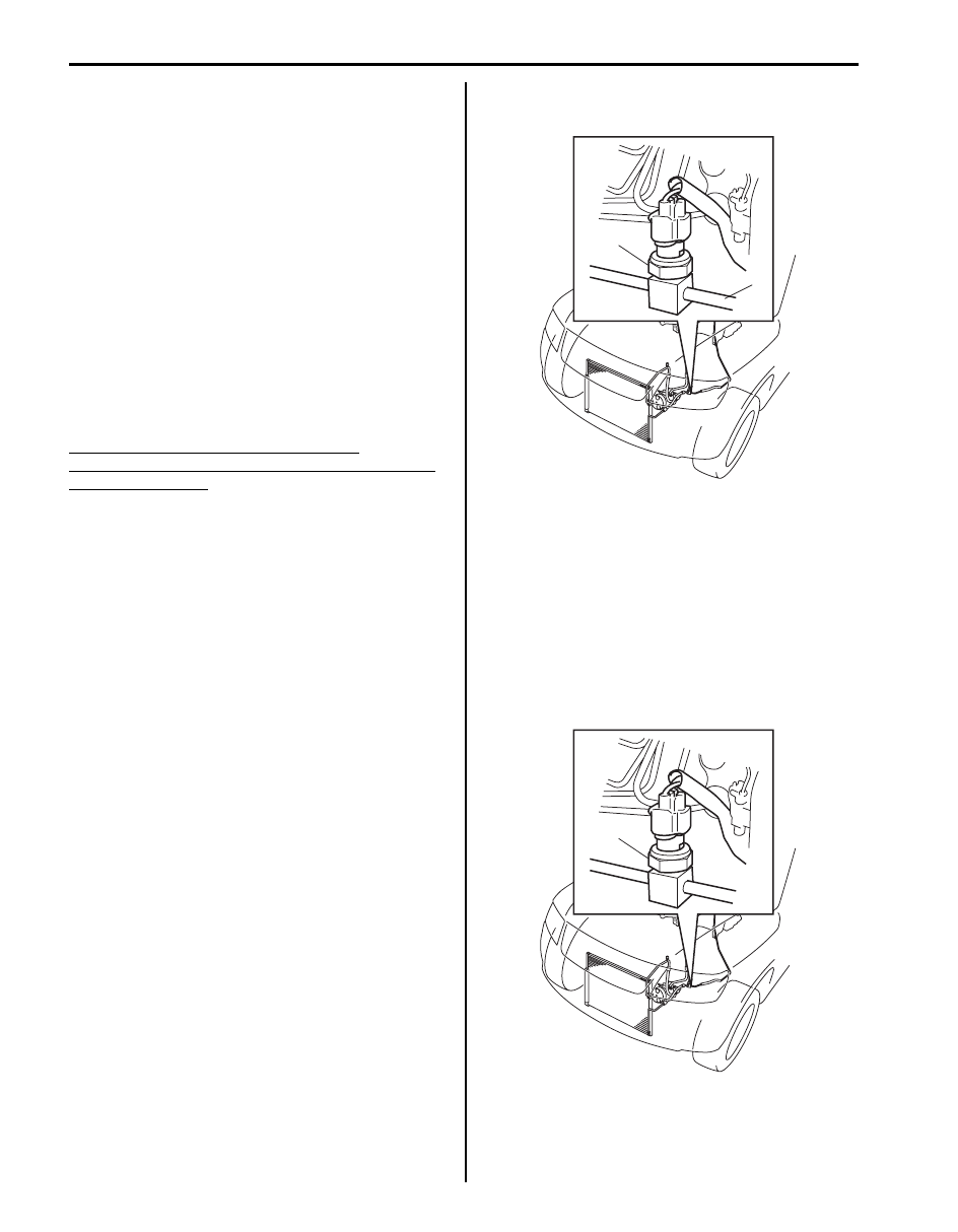
3) Disconnect A/C refrigerant pressure sensor
connector.
4) Remove A/C refrigerant pressure sensor (1) from
liquid pipe (2).
Installation
Reverse removal procedure noting the following
instructions.
• Apply compressor oil to O-ring of A/C refrigerant
pressure sensor.
• Tighten A/C refrigerant pressure sensor (1) to
specified torque.
Tightening torque
A/C refrigerant pressure sensor (a): 11 N·m (1.1
kgf-m, 8.0 lb-ft)
• Evacuate and charge the A/C system referring to
“Evacuation” and “Charge” in “Operation Procedure
for Charging A/C with Refrigerant”.
1
2
I5JB0A720049-03
1, (a)
I5JB0A720050-03
Air Conditioning System: 7B-73
Sunload Sensor Removal and Installation
S6JB0B7206017
Removal
1) Disconnect negative (–) cable at battery.
2) Detach sunload sensor (1) located on the driver side
of the dashboard (3). Be careful not to damage the
sensor and dashboard by using rag (2).
3) Disconnect connector (1) from sunload sensor (2).
Installation
Reverse removal procedure.
Sunload Sensor Inspection
S6JB0B7206018
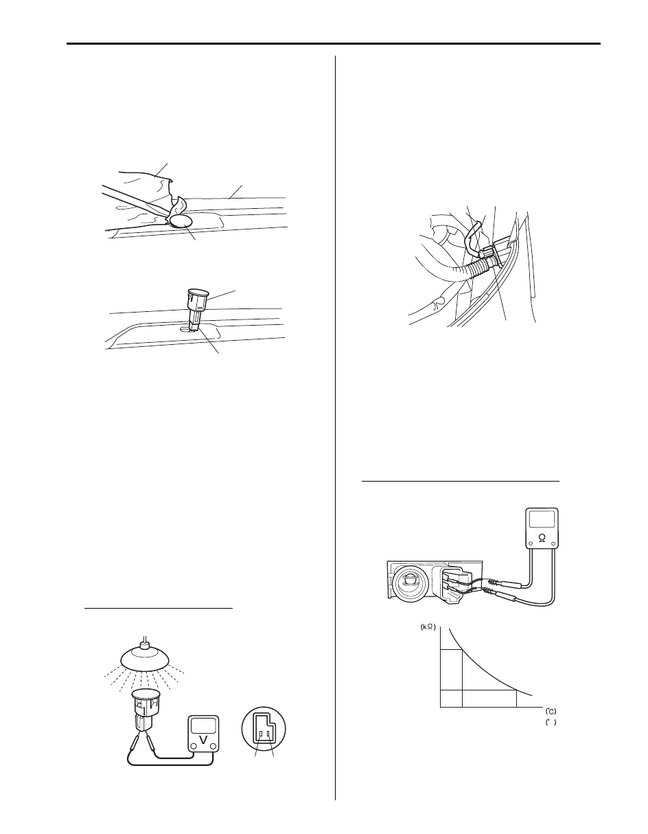
1) Remove sunload sensor. Refer to “Sunload Sensor
2) Light over the sensor vertically with an incandescent
light of approximately 100 watt.
3) The distance between the sensor and the light
should be approximately 100 mm (3.94 in.).
4) Measure the voltage between the terminals with the
(+) probe on the terminal “a” and the (–) probe on the
terminal “b”.
5) Make sure if the voltage is approximately 0.38 – 0.42
V. If not, replace the sensor with the new one.
Sunload sensor specifications
“a” – “b”: Approx. 0.38 – 0.42 V
Inside Air Temperature Sensor Removal and
Installation
S6JB0B7206019
Removal
1) Disconnect negative cable (–) at battery.
2) Remove steering column hole cover.
3) Disconnect inside air temperature sensor connector
(1) and aspirator hose (2).
4) Remove inside air temperature sensor (3) from
vehicle.
Installation
Reverse removal procedure.
Inside Air Temperature Sensor Inspection
S6JB0B7206020
1) Remove Inside air temperature sensor referring to
“Inside Air Temperature Sensor Removal and
Installation”.
2) Check resistance between terminals.
Inside air temperature sensor resistance
Approx. 1.7 k
Ω ± 85 Ω at 25 °C (77 °F)
2
1
3
I5JB0A720051-01
1
2
I5JB0A720052-01
“b”
“a”
I5JB0A720053-01
2
3
1
I5JB0A720054-01
Temperature
Resistance
1.7
0
32
25
77
F
5.5
I5JB0A720055-01
7B-74 Air Conditioning System:
Outside Air Temperature Sensor Removal and
Installation
S6JB0B7206021
Refer to “Outside Air Temperature Sensor Removal and
Installation (If Equipped) in Section 9C”.
Outside Air Temperature Sensor Inspection
S6JB0B7206022
Refer to “Outside Air Temperature Sensor Inspection (If
Equipped) in Section 9C”.
Air Flow Control Actuator Removal and
Installation
S6JB0B7206023
Refer to “Air Flow Control Actuator Removal and
Installation in Section 7A”.
Air Flow Control Actuator Inspection
S6JB0B7206024
Refer to “Air Flow Control Actuator Inspection in Section
7A”.
Air Intake Control Actuator Removal and
Installation
S6JB0B7206025
Refer to “Air Intake Control Actuator Removal and
Installation in Section 7A”.
Air Intake Control Actuator Inspection
S6JB0B7206026
Refer to “Air Intake Control Actuator Inspection in
Section 7A”.
Temperature Control Actuator Removal and
Installation
S6JB0B7206027
Refer to “Temperature Control Actuator Removal and
Installation in Section 7A”.
Temperature Control Actuator Inspection
S6JB0B7206028
Refer to “Temperature Control Actuator Inspection in
Section 7A”.
HVAC Control Module Removal and Installation
S6JB0B7206029
Refer to “HVAC Control Module Removal and Installation
in Section 7A”.
A/C Compressor Drive Belt Inspection and
Adjustment
S6JB0B7206030
Refer to “P/S Pump and A/C Compressor (If Equipped)
Drive Belt Inspection and Adjustment in Section 6C”.
A/C Compressor Drive Belt Removal and
Installation
S6JB0B7206031
Refer to “P/S Pump and A/C Compressor (If Equipped)
Drive Belt Removal and Installation in Section 6C”.
A/C Compressor Relay Inspection
S6JB0B7206032
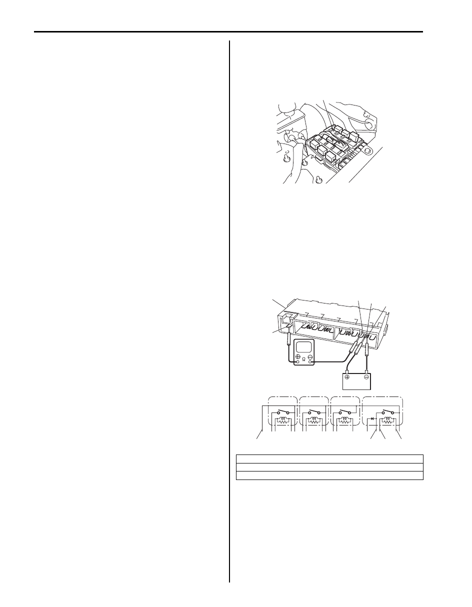
1) Disconnect negative (–) cable at battery.
2) Remove included in integration relay No.2 (1) from
vehicle.
3) Check that there is no continuity between terminals
“C” and “D”.
If there is continuity, replace integration relay No.2
(1).
4) Connect battery positive (+) terminal to terminal “B”
of relay. Connect battery negative (–) terminal to
terminal “A” of relay. Check for continuity between
terminal “C” and “D”. If there is no continuity when
relay is connected to the battery, replace integration
relay No.2 (1).
[A]: A/T relay
[B]: HO2S heater relay
[C]: Compressor relay
1
I5JB0A720057-01
“D”
“C”
[A]
[B]
[C]
1
“B”
“A”
“C”
“D”
“B”
“A”
I6JB01720008-01

Air Conditioning System: 7B-75
Compressor Assembly On-Vehicle Inspection
S6JB0B7206033
1) Install manifold gauge set (1) as shown in the figure.
2) Close Hi (4) and Lo (5) side valves.
3) Run engine at fast idle.
4) Check compressor for the following items.
If any of the checks indicated a defect, repair
compressor.
• High pressure gauge reading is not low and low
pressure gauge reading is not higher than normal.
• Metallic sound
• Leakage from compressor
Compressor Assembly Removal and
Installation
S6JB0B7206034
Removal
1) Run engine at idle with A/C ON for 10 minutes.
2) Disconnect negative (–) cable at battery.
3) Recover refrigerant from the A/C system using
recovery and recycling equipment referring to
“Recovery” in “Operation Procedure for Charging A/
C with Refrigerant”.
NOTE
The amount of compressor oil at removed
must be measured and the same amount
must be poured when installing the
compressor.
4) Drain engine coolant.
5) Remove radiator inside hose and outside hose from
vehicle.
6) Remove radiator cooling fan assembly referring to
“Radiator Cooling Fan Assembly Removal and
Installation in Section 1F”.
7) Remove drive belt referring to “P/S Pump and A/C
Compressor (If Equipped) Drive Belt Removal and
Installation in Section 6C”.
8) Disconnect magnet clutch connector.
9) Disconnect suction hose and discharge hose from
compressor.
NOTE
Cap open fitting immediately to keep
moisture out of system.
10) Remove compressor from its mount.
Installation
CAUTION
!
Be sure to use HFC-134a (R-134a)
compressor oil.
Reverse removal procedure noting the following
instructions.
• If compressor is replaced, pour new compressor oil
referring to “Precautions on Replenishing Compressor
Oil”.
• Install drive belt referring to “P/S Pump and A/C
Compressor (If Equipped) Drive Belt Removal and
Installation in Section 6C”.
• Install radiator cooling fan assembly referring to
“Radiator Cooling Fan Assembly Removal and
Installation in Section 1F”.
• Fill engine coolant to radiator.
• Evacuate and charge system referring to “Evacuation”
and “Charge” in “Operation Procedure for Charging A/
C with Refrigerant”.
Tightening torque
Compressor mounting bolt: 25 N·m (2.5 kgf-m,
18.0 lb-ft)
2. High pressure side (Delivery side hose)
3. Low pressure side (Suction side pipe)
1
5
3
4
2
I5JB0A720059-01
Нет комментариевНе стесняйтесь поделиться с нами вашим ценным мнением.
Текст