Suzuki Grand Vitara JB627. Manual — part 155
3C-24 Transfer:
4WD Control Symptom Diagnosis
S6JB0B3304011
Diagnose transfer assembly after performing the following inspections.
1) Perform 4WD control system check referring to “4WD Control System Check”.
2) Confirm 4WD control system operation referring to “4WD Control System Operation”
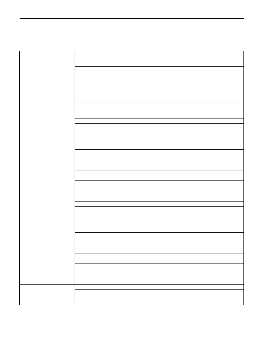
Condition
Possible cause
Correction / Reference Item
Transfer does not operate
(Transfer position
indicator does not
operate)
Transfer switch faulty
Check switch referring to “Transfer Switch
Inspection”.
Transfer shift actuator faulty
Check transfer shift actuator referring to
“Transfer Assembly Inspection”.
4L/N switch and/or switch center
differential lock switch faulty
Check switch referring to “Transfer Assembly
Inspection”.
Transmission range sensor (“N” range)
faulty (for A/T model)
Adjust or check transmission range sensor
referring to “Transmission Range Sensor
Inspection and Adjustment in Section 5A”.
CPP switch faulty (for M/T model)
Check CPP switch referring to “Clutch Pedal
Position (CPP) Switch Inspection and
Adjustment in Section 5C”.
Wiring or grounding faulty
Repair as necessary.
4WD control module faulty
Check 4WD control module referring to
“Inspection of 4WD Control Module and Its
Circuits”.
Transfer refuses to
operate (Transfer position
indicator flashes, and
then transfer does not
shift)
Transfer shift actuator faulty
Check transfer shift actuator referring to
“Transfer Assembly Inspection”.
4L/N switch and/or center differential
lock switch faulty
Check switch referring to “Transfer Assembly
Inspection”.
Distorted control cover shift shaft or shift
fork
Check shift fork referring to “Transfer Assembly
Inspection”.
Weakened control cover shift shaft
spring
Check spring referring to “Transfer Assembly
Inspection”.
Distorted or dispositioned control cover
shift shaft snap ring and washer
Check snap ring and washer referring to
“Transfer Assembly Inspection”.
Worn chamfered tooth on sleeve or gear Check chamfered tooth and gear referring to
“Transfer Assembly Inspection”.
Wiring or grounding faulty
Repair as necessary.
4WD control module faulty
Check 4WD control module referring to
“Inspection of 4WD Control Module and Its
Circuits”.
Gear slipping out of mesh Worn control cover shift shaft
Check control cover shift shaft referring to
“Transfer Assembly Inspection”.
Worn shift fork or sleeve
Check shift fork or sleeve referring to “Transfer
Assembly Inspection”.
Weak or damaged control cover shift
shaft spring
Check spring referring to “Transfer Assembly
Inspection”.
Worn bearings on input gear or counter
gear
Check bearing referring to “Transfer Assembly
Inspection”.
Worn chamfered tooth on sleeve or gear Check sleeve and gear referring to “Transfer
Missing or disengagement of circlip(s)
Check circlip(s) referring to “Transfer Assembly
Inspection”.
Noise
Damaged or worn bearing(s)
Refer to “Transfer Assembly Inspection”.
Damaged or worn gear(s)
Refer to “Transfer Assembly Inspection”.
Damaged or worn chamfered tooth on
sleeve or gear

Transfer: 3C-25
Transfer Position Indicator Does Not Come ON at Ignition Switch ON but Engine Stops
S6JB0B3304012
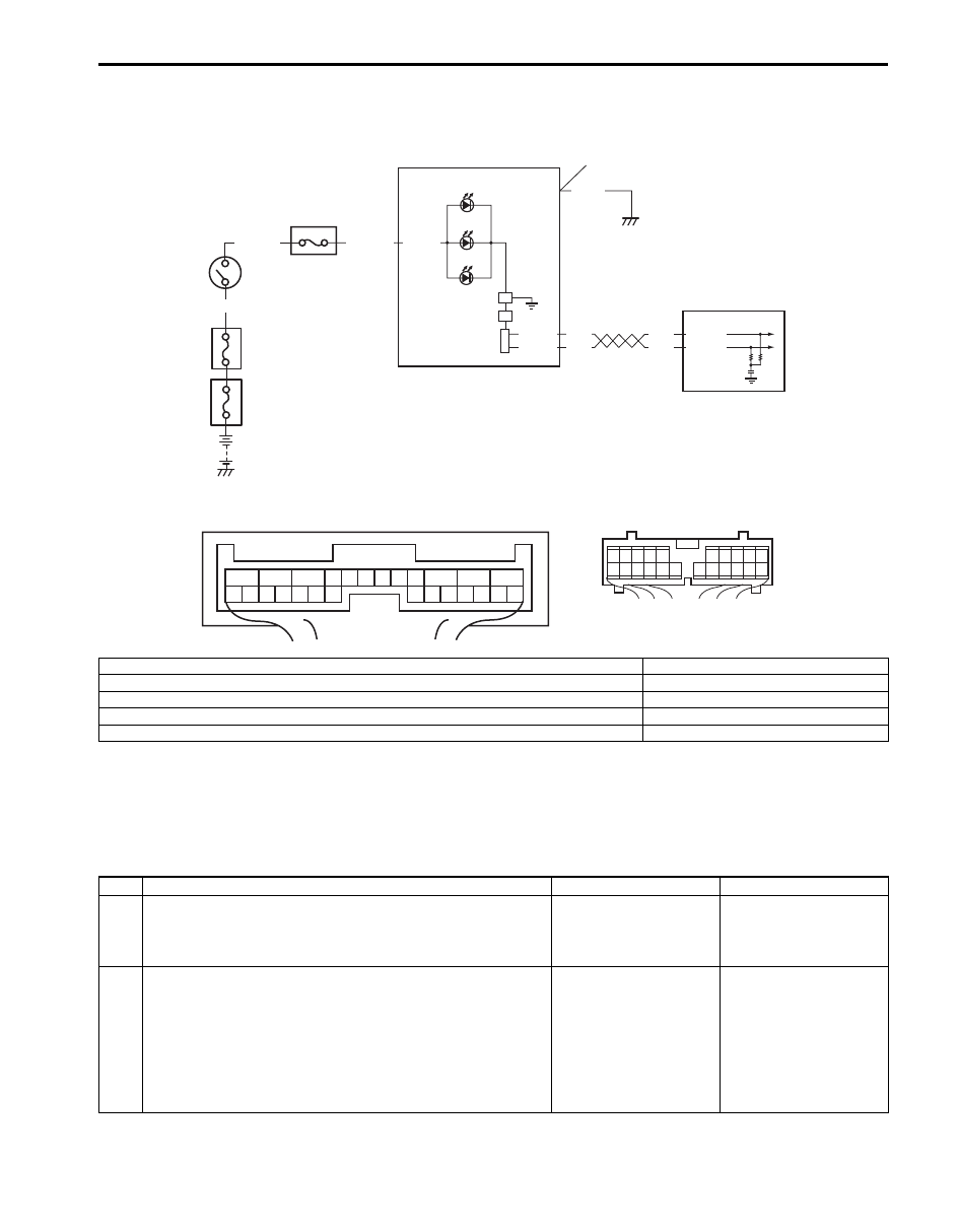
Wiring Diagram
Circuit Description
Transfer position indicator operates according to the signal from 4WD control module. If the transfer control system is
in good condition, transfer position indicator light up for 2 seconds when ignition switch is turned to ON position, and
then turned to OFF position. If an abnormality is detected in the system, transfer position indicator remains lighting.
E91-22
E91-23
RED
WHT
RED
WHT
G28-10
G28-8
1
2
G28-13
PPL/RED
BLK
WHT/GRN
BLK/YEL
8
G28-15
4
6
7
5
3
1
2
3
4
5
6
7
8
9
10
11
17
1615141312
2221201918
[B]
1
2
3
4
5
6
7
8
9
10
11
12
13
14
15
16
17
18
19
20
21
22
23
24
25
26
[A]
I5JB0A332015-03
[A]: 4WD control module connector “E91” (viewed from harness side)
4. 4L indicator
[B]: Combination meter connector (viewed from harness side)
5. N indicator
1. 4WD control module
6. Junction block assembly
2. Combination meter
7. “METER” fuse
3. Differential lock indicator
8. Ignition switch

3C-26 Transfer:
Troubleshooting
Step
Action
Yes
No
1
Transfer position indicator power supply check
1) Turn ignition switch to ON position.
Do other indicators come ON?
Go to Step 2.
Go to Step 3.
2
Check DTC
1) Connect scan tool to DLC with ignition switch OFF.
2) Turn ignition switch to ON position and check DTC.
Is there DTC(s) U1073, U1100, U1101 and/or U1121?
Go to applicable DTC
diag. flow.
Substitute a known-
good combination meter
and recheck. If transfer
position indicator still
remains off, substitute a
known-good 4WD
control module and
recheck.
3
CAN communication circuit check
1) Check CAN communication circuit between combination
meter and 4WD control module referring to “DTC U1073:
Control Module Communication Bus Off”.
Is CAN communication circuit in good condition?
Go to Step 4.
Repair or replace.
4
“METER” fuse check
1) Turn ignition switch to OFF position.
2) Check for fuse blown to “METER” fuse in junction block
assembly.
Is “METER” fuse in good condition?
Go to Step 5.
Replace “METER” fuse
and check for short.
5
Combination meter power supply check
1) Remove combination meter referring to “Combination
Meter Removal and Installation in Section 9C”.
2) Check proper connection to combination meter
connector at “G28-13” and “G28-15” terminals.
3) If OK, then turn ignition switch to ON position and
measure voltage between combination meter connector
at “G28-13” terminal and vehicle body ground.
Is it 10 – 14 V?
Go to Step 6.
“PPL/RED” wire is open
circuit.
6
Combination meter ground circuit check
1) Turn ignition switch to OFF position.
2) Measure resistance between combination meter
connector at “G28-15” terminal and vehicle body ground.
Is resistance 1
Ω
or less?
Substitute a known-
good combination meter
and recheck. If transfer
position indicator still
remains OFF, substitute
a known-good 4WD
control module and
recheck.
“BLK” wire is open or
high resistance circuit.
Transfer: 3C-27
Transfer Position Indicator Remains ON Steady at Ignition Switch ON
S6JB0B3304013
Wiring Diagram
Circuit Description
Transfer position indicator operates according to the signal from 4WD control module. If the transfer control system is
in good condition, transfer position indicator light up for 2 seconds when ignition switch is turned to ON position, and
then turned to OFF position. If an abnormality is detected in the system, transfer position indicator remains lighting.
Troubleshooting
E91-22
E91-23
RED
WHT
RED
WHT
G28-10
G28-8
1
2
G28-13
PPL/RED
BLK
WHT/GRN
BLK/YEL
8
G28-15
4
6
7
5
3
1
2
3
4
5
6
7
8
9
10
11
17
1615141312
2221201918
[B]
1
2
3
4
5
6
7
8
9
10
11
12
13
14
15
16
17
18
19
20
21
22
23
24
25
26
[A]
I5JB0A332015-03
[A]: 4WD control module connector “E91” (viewed from harness side)
4. 4L indicator
[B]: Combination meter connector (viewed from harness side)
5. N indicator
1. 4WD control module
6. Junction block assembly
2. Combination meter
7. “METER” fuse
3. Differential lock indicator
8. Ignition switch
Step
Action
Yes
No
1
Check DTC
1) Check DTC referring to “DTC Check”.
Is there any DTC(s)?
Perform DTC flow to
repair and retry.
Go to Step 2.
2
CAN communication circuit check
1) Check CAN communication circuit between combination
meter and 4WD control module referring to “DTC U1073:
Control Module Communication Bus Off”.
Is CAN communication circuit in good condition?
Substitute a known-
good combination meter
and recheck. If transfer
position indicator still
remains off, substitute a
known-good 4WD
control module and
recheck.
Repair or replace.
Нет комментариевНе стесняйтесь поделиться с нами вашим ценным мнением.
Текст