Suzuki Grand Vitara JB627. Manual — part 154
3C-20 Transfer:
DTC Clearance
S6JB0B3304006
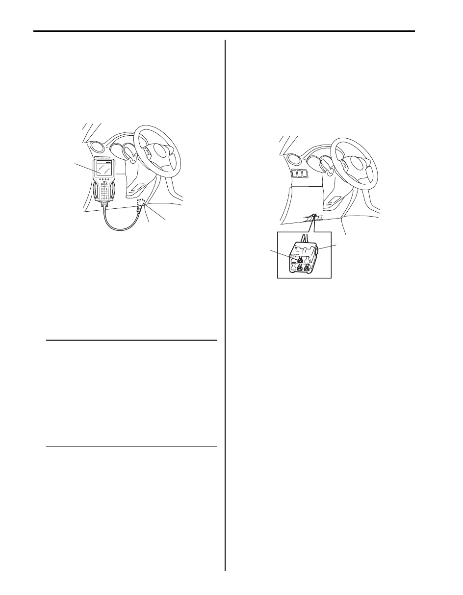
Using SUZUKI Scan Tool
1) Turn ignition switch to OFF position.
2) Connect SUZUKI scan tool to data link connector
(DLC) (1) located on underside of instrument panel.
Special tool
(A): SUZUKI scan tool
3) Turn ignition switch to ON position.
4) Erase DTC according to instructions displayed on
SUZUKI scan tool. Refer to SUZUKI scan tool
operator’s manual for further details.
5) After completing clearance, turn ignition switch OFF
and disconnect SUZUKI scan tool from data link
connector (DLC).
6) Perform “DTC Check” and confirm that NO CODES
is displayed.
NOTE
DTC and freeze frame data stored in 4WD
control module memory are also cleared in
the following cases. Be careful not to clear
them before keeping their record.
• When power to 4WD control module is cut
off (by disconnecting battery cable,
removing fuse or disconnecting 4WD
control module connectors).
• When the same malfunction (DTC) is not
detected again during 40 engine warm-up
cycles.
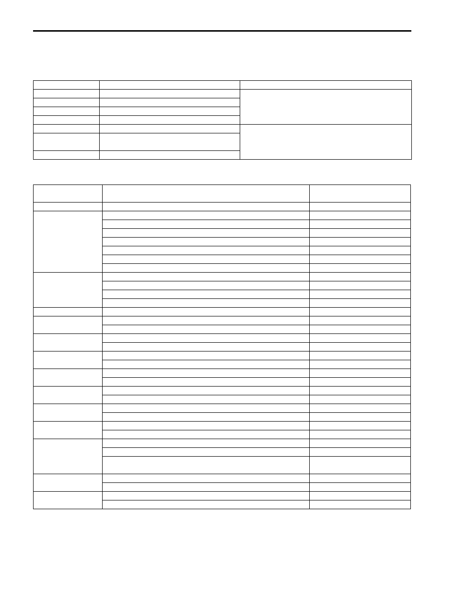
Using Diagnosis Connector
1) Turn ignition switch to ON position.
2) Using service wire short diagnosis switch terminal
(1) of diagnosis connector (2) and body ground more
than 5 times at about 1 second interval within 10
seconds.
3) Wait more than 9 seconds.
4) Perform “DTC Check” and confirm that DTC No. is
not displayed.
(A)
1
I5JB0A332012-01
1
2
I5JB0A332014-01

Transfer: 3C-21
DTC Table
S6JB0B3304007
NOTE
“O” in transfer position indicator column of the above table means indicator lights up when DTC is
detected.
DTC No.
Detecting item
Detecting condition
(DTC will set when detecting)
Transfer
position
indicators
Transfer switch circuit open
Different switch combination from specification is
detected.
{
Transfer switch circuit short
Different switch combination from specification is
detected.
{
Transfer shift actuator motor
position switch 1 circuit open
Actuator position switch signal voltage 4.2 V or
more.
{
Transfer shift actuator motor
position switch 1 circuit short
Actuator position switch signal voltage 0.6 V or
less.
{
4L/N switch circuit open
Though actuator position switch is “4L-lock”
position, the ON signal is not input from the 4L/N
switch.
{
4L/N switch circuit short
Though actuator position switch is “4L-lock”
position, the OFF signal is not input from the 4L/
N switch.
{
Transfer actuator circuit
malfunction
• Position switch in transfer shift actuator is not
changed for 3 seconds even if command
signal of motor relay for transfer shift actuator
(included in 4WD control module) is turned on.
or
• Monitor signal from motor relay of transfer
shift actuator (included in 4WD control
module) is inconsistent with command signal
to motor relay of transfer shift actuator.
{
Transfer shift actuator motor
position switch 2 circuit open
Actuator position switch signal voltage 4.2 V or
more.
{
Transfer shift actuator motor
position switch 2 circuit short
Actuator position switch signal voltage 0.6 V or
less.
{
Center differential lock switch
circuit open
Though actuator position switch is “4H” position,
the ON signal is not input from the center
differential lock switch.
{
Center differential lock switch
circuit short
Though actuator position switch is “4L-lock”
position, the OFF signal is not input from the
center differential lock switch.
{
4WD control module power
supply circuit malfunction
Battery voltage is lower than lower limit voltage
for 4WD control module diagnosis.
{
Internal circuit malfunction of
4WD control module
EEPROM error
{
Clutch pedal position (CPP)
switch circuit short
CPP switch signal is input when vehicle speed is
30 km/h (19 mph).
{
Control module communication
bus off
Transmitting and receiving error of 4WD control
module for specified time continuously.
{
U1100
Lost communication with ECM
Receiving error of 4WD control module from
ECM for specified time continuously.
{
U1101
Lost communication with TCM
Receiving error of 4WD control module from
TCM for specified time continuously.
{
U1121
Lost communication with ABS /
electronic stability program
control module
Receiving error of 4WD control module from
ABS / electronic stability program control module
for specified time continuously.
{
3C-22 Transfer:
Fail-Safe Table
S6JB0B3304008
This function is provided by the safe mechanism that assures safe drive ability even when the actuator, switch, sensor
or its circuit fails. The following table shows the fail safe function for each fail condition of sensor, actuator, switch,
4WD control module or its circuit.
Scan Tool Data
S6JB0B3304009
DTC No.
Trouble Area
Fail-Safe Operation
Transfer actuator switch 1 circuit open
4WD control module stops outputting of control
signal to transfer actuator (When shifting, it stops
outputting after shifting is completed).
Transfer actuator switch 1 circuit short
Transfer actuator switch 2 circuit open
Transfer actuator switch 2 circuit short
C1230
Transfer actuator circuit malfunction
4WD control module stops outputting of control
signal to transfer actuator.
C1240
4WD control module power supply circuit
malfunction
Clutch switch circuit short
Scan Tool Data
Vehicle Condition
Normal Condition /
Reference Value
Vehicle speed
At vehicle stop
0 km/h, 0 mph
Actuator Pos Sen
Transfer shifted to 4H position
4H
Transfer being shifted between 4H-lock and 4H position
4H-lock – 4H
Transfer shifted to 4H-lock position
4H-lock
Transfer being shifted between 4H and N position
4H – N
Transfer shifted to 4L-lock position
4L-lock
Transfer being shifted between N and 4L-lock position
N – 4L-lock
Transfer shifted to N position
N
Actuator motor Pos
Transfer shifted to 4H position
4H
Transfer shifted to 4H-lock position
4H-lock
Transfer shifted to 4L-lock position
4L-lock
Transfer shifted to N position
N
Battery voltage
Ignition switch ON and engine stop
10 – 14 V
4L/N switch
Transfer shifted to 4L-lock or N position
ON
Transfer shifted to 4H or 4H-lock position
OFF
Center diff lock SW
Transfer shifted to 4H or N position
ON
Transfer shifted to 4H-lock or 4L-lock position
OFF
N range signal (AT)
A/T shifted to “N” range
ON
A/T shifted to other than “N” range
OFF
CPP switch (MT)
Clutch pedal depressed
OFF
Clutch pedal released
ON
Mode switch 1
Transfer switch selected to N position
ON
Transfer switch selected to 4H, 4H-lock or 4L-lock position
OFF
Mode switch 2
Transfer switch selected to 4H, 4H-lock or N position
ON
Transfer switch selected to 4L-lock position
OFF
Mode switch 3
Transfer switch selected to 4H-lock or 4L-lock position
ON
Transfer switch selected to 4H or N position
OFF
Warning buzzer
Buzzer not being sound
OFF
Transfer shifted to N Position
N Pos
Transfer shifted to disagreement of transfer switch and transfer
position
Error
ABS active
ABS operating
ON
ABS not operating
OFF
ESP
® active
ESP
® operating
ON
ESP
® not operating
OFF
Transfer: 3C-23
Scan Tool Data Definitions
S6JB0B3304010
Vehicle Speed (KM/H, MPH):
This parameter indicates vehicle speed calculated by 4WD control module.
Actuator Pos Sen (Transfer shift actuator motor position switch) (4H / 4H-lock / 4L-lock / N / 4H-lock-4H / 4H-N
/ N-4L-lock):
This parameter indicates transfer shift actuator motor position switch status detected by 4WD control module.
Actuator motor Pos (Transfer shift actuator motor position) (4H / 4H-lock / 4L-lock / N):
This parameter indicates transfer shift actuator motor position detected by 4WD control module using transfer shift
actuator motor position.
Battery voltage (V):
This parameter indicates battery voltage detected by 4WD control module.
4L / N switch (ON / OFF):
This parameter indicates 4L / N switch status detected by 4WD control module.
Center diff lock Sw (ON / OFF):
This parameter indicates center differential lock switch status detected by 4WD control module.
N range signal (AT) (ON / OFF):
This parameter indicates A/T shift position (“N” range or not) detected by 4WD control module.
CPP switch (Clutch pedal position switch) (MT) (ON / OFF):
This parameter indicates clutch pedal position switch status detected by 4WD control module using CPP switch.
Mode switch 1 (Transfer switch) (ON / OFF):
ON: Transfer switch to N position.
OFF: Transfer switch to other than N position.
Mode switch 2 (Transfer switch) (ON / OFF):
ON: Transfer switch to other than 4L-lock position.
OFF: Transfer switch to 4L-lock position.
Mode switch 3 (Transfer switch) (ON / OFF):
ON: Transfer switch to 4H-lock or 4L-lock position.
OFF: Transfer switch to 4H or N position.
Warning buzzer (OFF / N Pos / Error):
This parameter indicates if buzzer is being commanded by 4WD control module.
ABS active (ON / OFF):
This parameter indicates ABS status detected by 4WD control module.
ESP
® active (ON / OFF):
This parameter indicates ESP
® status detected by 4WD control module.
Нет комментариевНе стесняйтесь поделиться с нами вашим ценным мнением.
Текст