Suzuki Grand Vitara JB627. Manual — part 422
10B-37 Body Electrical Control System:
DRL Function Setting Procedure
S6JB0BA206004
DRL is controlled by BCM which has a function to set
operable / non-operable mode of DRL. With a new BCM,
its DRL is set to the non-operable mode.
Therefore, when BCM has been replaced in the country
where DRL operation is required by the statutory
regulation, set DRL to the operable mode according to
the procedure described below.
Also, performing the same procedure when DRL is in the
operable mode will change DRL setting to the non-
operable mode.
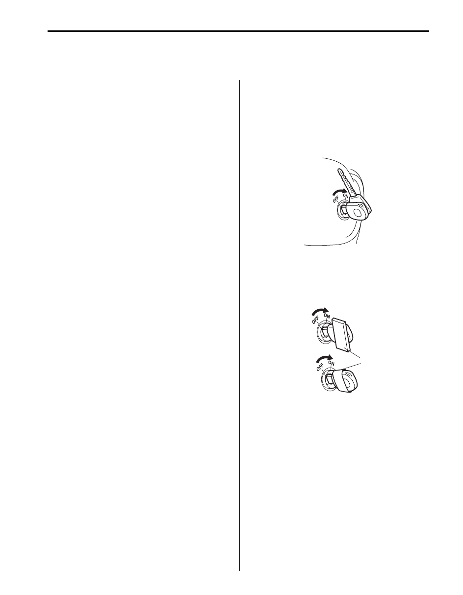
1) Turn ignition switch to ON position.
2) Perform Steps a) through f) described blow within 15
seconds after Step 1).
a) Turn lighting switch to CLEARANCE position.
b) Turn lighting switch to OFF position.
c) Repeat Steps a) and b) five times.
d) Turn lighting switch to HEAD position.
e) Turn lighting switch to OFF position.
f) Repeat Steps a) and e) five times.
3) After Step f), buzzer sounds twice which indicates
that DRL has been set to operable mode.
NOTE
When DRL setting has been changed from
operable mode to non-operable mode, buzzer
sounds once.
4) After confirming buzzer, turn ignition switch to OFF
position.
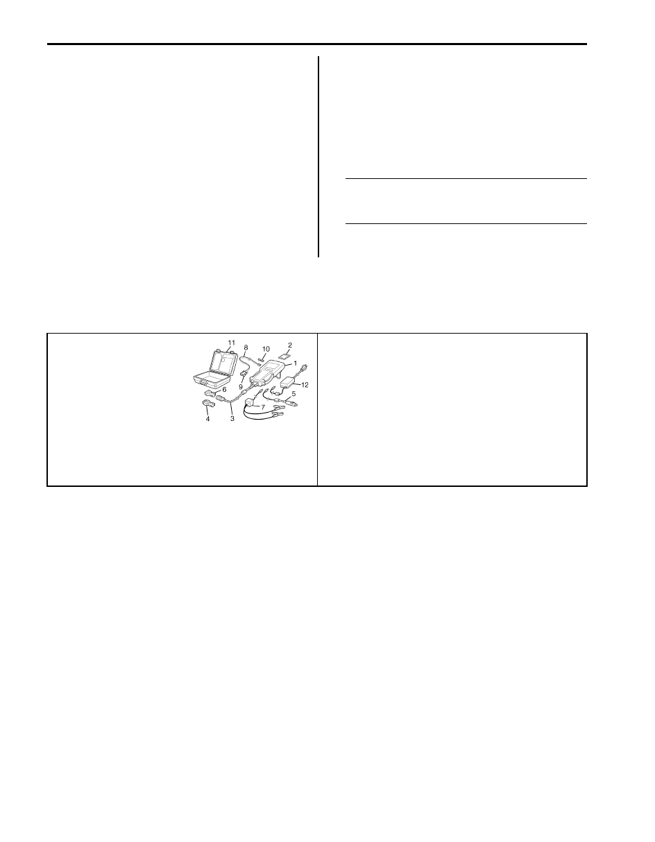
Special Tools and Equipment
Special Tool
S6JB0BA208001
SUZUKI scan tool
—
This kit includes following
items. 1. Tech 2, 2. PCMCIA
card, 3. DLC cable, 4. SAE
16/19 adapter, 5. Cigarette
cable, 6. DLC loop back
adapter, 7. Battery power
cable, 8. RS232 cable, 9.
RS232 adapter, 10. RS232
loop back connector, 11.
Storage case, 12. )
Immobilizer Control System: 10C-1
Control Systems
Immobilizer Control System
Precautions
Precautions in Diagnosing Troubles
S6JB0BA300001
• Before confirming the diagnostic trouble code (DTC),
do not disconnect connector from ECM, battery cable
from battery, ground wire harness, or main fuse. Such
disconnection will erase DTC stored in ECM.
• DTC stored in ECM memory can be checked as well
as cleared by using SUZUKI scan tool. Before using
SUZUKI scan tool, read its operator’s manual
carefully to know how to use it and what functions are
available.
• Be sure to read “Precautions for Electrical Circuit
Service in Section 00” before inspection.
• Communication of ECM, BCM, combination meter,
TCM, keyless start control module (if equipped), ABS/
ESP
® control module, 4WD control module (if
equipped), Steering angle sensor (if equipped) and
DLC is established by CAN (Computer Area Network).
(For more detail of CAN communication, refer to “CAN
Communication System Description in Section 1A”)
Therefore, handle CAN communication lines with care
referring to “Precaution for CAN Communication
System in Section 00”.
Precaution in Replacing ECM
S6JB0BA300002
• If ECM is replaced with new or used one without the
functionality for the immobilizer control system, the
engine will not be started. In case of the above, check
if the newly installed ECM has the functionality for the
immobilizer control system referring to its part
number.
• After ECM is replaced with new one or used one, the
transponder code in the transponder built in the
ignition key has to be registered with ECM. Or, the
engine cannot be started up. For the registration
procedure, refer to “Procedure after ECM
Replacement”.
Precautions in Handling Immobilizer Control
System
S6JB0BA300003
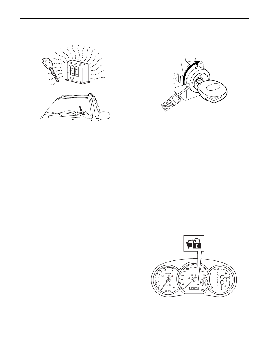
• Do not turn ON ignition switch with ignition key in
contact with another one or quite close to another
one. Or, the immobilizer control system may detect
some abnormal condition and prevent the engine from
starting.
• Do not turn ON ignition switch by using ignition key
with any type of metal (1) wrapped its grip or in
contact with it. Or, the immobilizer control system may
detect some abnormal condition and prevent the
engine from starting.
I3RH0AA30001-01
1
I3RH0AA30002-01
10C-2 Immobilizer Control System:
• Do not leave ignition key in a place where
temperature is high. High temperature may cause
damage to the transponder built in the ignition key.
• Do not turn ignition switch to ON position by bringing
radio antenna close to coil antenna. Or, the
immobilizer control system may detect some
abnormal condition and prevent the engine from
starting.
General Description
Immobilizer Control System Introduction
S6JB0BA301001
The immobilizer control system is an anti-theft device
that immobilizes the vehicle. It stops the engine from
working and prevents the vehicle from being stolen. It
mainly consists of the following components.
• Engine Control Module (ECM)
• Immobilizer control module (ICM) with the built-in coil
antenna
• Ignition key with the built-in transponder
A code called the transponder code is memorized in the
transponder. And, the code is registered with ECM.
Basically, when the ignition switch is turned ON, ECM
reads the code by the coil antenna. Then, if the code in
transponder in the ignition key does not match with the
one registered with ECM, ECM stops the operation of
the fuel injection so as not to start up the engine and
turns the immobilizer indicator light ON and OFF using
CAN communication lines. (In addition to the above
operation, ECM also turns the immobilizer indicator light
ON and OFF when some trouble is detected in the
keyless start system.)
On-Board Diagnostic System Description (Self-
diagnosis Function)
S6JB0BA301003
ECM diagnoses if there is any trouble with the
immobilizer control system. The diagnostic information is
stored as the diagnostic trouble code (DTC) in ECM. To
read the diagnostic information, use SUZUKI scan tool
referring to “Diagnostic Trouble Code (DTC) Check”.
With the ignition switch turned ON (but the engine at
stop) regardless of the condition of the engine and
emission control system, ECM indicates whether there is
any trouble with the immobilizer control system or not by
either lighting ON or flashing ON and OFF the
immobilizer indicator light.
Immobilizer indicator light lights ON:
No trouble exists in the immobilizer control system.
(After starting up the engine, the light turns OFF.)
Immobilizer indicator light flashes ON and OFF:
There is some trouble in the immobilizer control system
or in the keyless start system. Its diagnostic information
is stored in ECM.
I3RH0AA30003-01
I3RH0AA30004-01
I5JB0AA30002-01
Immobilizer Control System: 10C-3
Schematic and Routing Diagram
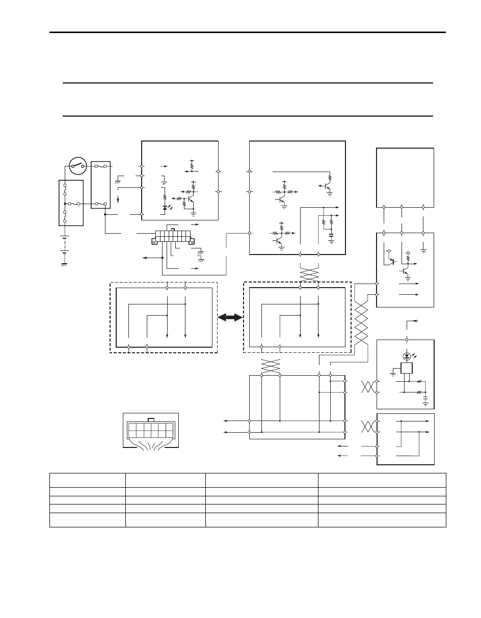
Immobilizer Control System Wiring Circuit Diagram
S6JB0BA302001
NOTE
For more details about power supply and ground wire circuits for ECM, BCM, ABS/ESP
® control
module, keyless start control module and combination meter, refer to “System Circuit Diagram in
Section 9A”.
BLK/WHT
BLK
WHT/BLU
WHT/RED
12V
G24-1
G24-2
12V
5V
12V
12V
PNK/BLU
GRY/BLU
G24-4
G24-3
E23-11
E23-19
BLK
BLK/YEL
12V
E23-29
WHT
PPL/WHT
E53-46 E53-42
E23-9 E23-17
WHT
RED
E53-13 E53-44
RED
WHT
RED
WHT
RED
WHT
G31-1
G31-3
G28-8
G28-10
G42-19
G42-18
G42-20 G42-29 G42-30
5V
ORN
BRN/YEL
BLK/YEL
G22-3 G22-7 G22-8
G28-13
PPL/RED
1
2
2
2
2
2
3
4
2
5
6
7
15
9
10
11
12
13
14
BLK
BLK/RED
G24-5
G24-6
14
E03-8
E03-10
E03-12 E03-6
8
19
1
2
3
4
G24
16
5
6
G31-2
G31-4
RED
WHT
WHT
RED
17
18
18
20
I5JB0DA30001-02
1. Battery
6. Data link connector (DLC)
11. Keyless start control module
16. Immobilizer control module (ICM) connector
(harness side view)
2. Fuse
7. ECM
12. Combination meter
17. To DLC
3. Ignition switch
8. ABS control module
13. From fuse
18. To BCM
4. Junction block assembly
9. Junction connector
14. BCM
19. To BCM and ABS/ESP
® control module
5. Immobilizer control
module (ICM)
10. Steering lock unit
15. ESP
® control module (Vehicle equipped
with ESP
® system)
20. To TCM, 4WD control module and steering
angle sensor (if equipped)
Нет комментариевНе стесняйтесь поделиться с нами вашим ценным мнением.
Текст