Suzuki Grand Vitara JB627. Manual — part 168
3D-3 Propeller Shaft:
Installation
Reverse removal procedure to install propeller shaft
noting the following points.
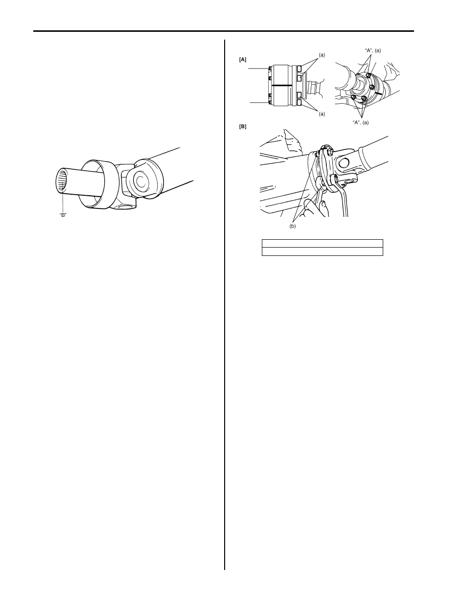
• Clean and inspect sliding portion of propeller shaft
end (where oil seal contacts) before installation and if
even small dent or scratch exists, correct end clean it
again.
Then apply grease inside splines of propeller shaft.
“B”: Grease 99000–25010 (SUZUKI Super Grease
A)
• Install propeller shaft aligning match marks.
Otherwise, vibration may occur during driving.
• Use the following specification to torque universal joint
flange nuts and bolts. For front propeller shaft flange
bolt (front differential side), apply thread lock cement
to thread part of bolts if reused.
• Fill transfer oil, if removed front propeller shaft
referring to “Transfer Oil Change in Section 3C”.
“A”: Thread lock cement 99000–32110 (Thread
Lock Cement Super 1322)
Tightening torque
Front propeller shaft flange bolt (a): 30 N·m (3.0
kgf-m, 22.0 lb-ft)
Rear propeller shaft flange nut (b): 85 N·m (8.5
kgf-m, 61.5 lb-ft)
IYSQ01521009-01
[A]: Front propeller shaft
[B]: Rear propeller shaft
I5JB0A340004-01
Propeller Shaft: 3D-4
Propeller Shaft Disassembly and Assembly
S6JB0B3406003
CAUTION
!
Never disassemble each joint.
Performing this prohibited service will affect
its original performance.
Disassembly
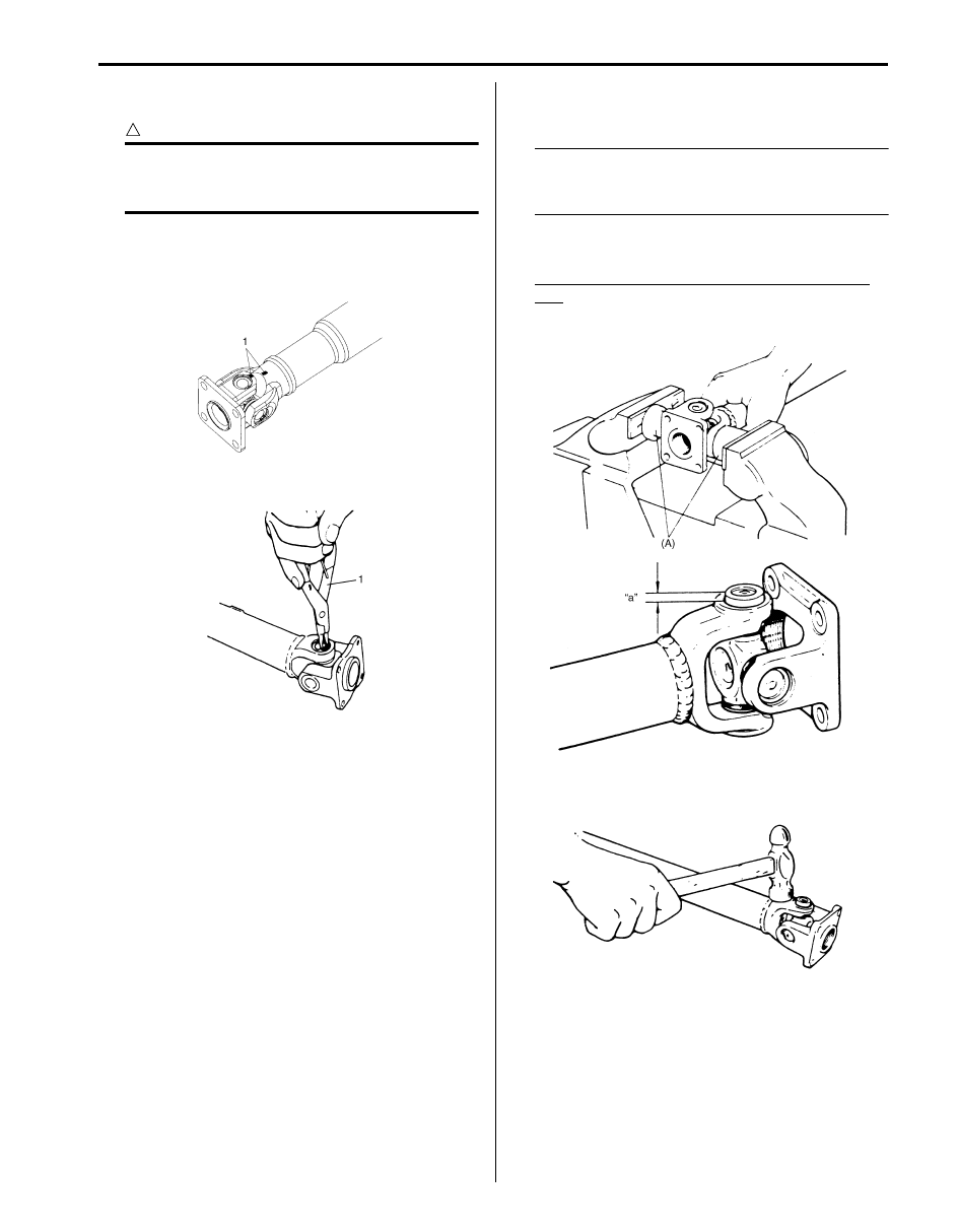
1) Give match marks (1) on flange yoke and shaft as
shown in the figure.
2) Using snap ring plier (1), remove 2 circlips.
3) Using special tool, push spider bearing race out 3 –
4 mm (0.12 – 0.16 in.) from shaft yoke race.
NOTE
Before pushing it out, apply penetrate
lubricant between bearing race (1) and yoke
race (2).
Special tool
(A): 09926-48010
Spider bearing race installing position (length
“a”)
“a”: 3 – 4 mm (0.12 – 0.16 in.)
4) Tapping yoke with a hammer, completely remove
bearing race.
I5JB0A340007-01
I5JB0A340005-02
I5JB0A340006-01
IYSQ01340007-01

3D-5 Propeller Shaft:
5) Take out bearing race on the other side in the same
way as in Step 3) and 4).
6) Push out bearing race on flange yoke side as
described in Step 2) and 3), and then, holding
bearing race in a vise (1), tap flange yoke and take
out race. (Refer to the figure.)
Remove bearing race on the opposite side in the
same way.
NOTE
• Take care not to lose rollers in spider
bearing race when removing it.
• Fit removed bearings temporarily in spider
so that they can be reinstalled in their
original positions.
Assembly
NOTE
Make sure that rollers inside spider bearing
race are all in place.
CAUTION
!
In assembly, be sure to use new circlips,
spider (1) and bearings (2). Reuse of circlips,
spider (1) and bearings (2) once assembled is
prohibited.
1) Make sure to apply grease to spider bearing race.
“A”: Grease 99000–25030 (SUZUKI Super
Grease C)
2) Insert bearing race into yoke, using press, until it is
flush with yoke face. When doing this, insert spider
into bearing race to prevent rollers in bearing race
from coming out.
3) Aligning match marks (1) and insert the other
bearing race on the opposite side into yoke, using
press until it is flush with yoke face.
4) Insert bearing races on the flange yoke side in the
same way as described in Step 1) and 2).
5) Securely fit 4 circlips to shaft and flange yoke.
NOTE
• Make sure that each circlip is fitted in
groove securely.
6) After assembly, check to ensure that both shaft yoke
and flange yoke move smoothly.
IYSQ01340008-01
IYSQ01340010-01
IYSQ01340009-01
I5JB0A340007-01
Propeller Shaft: 3D-6
Propeller Shaft Inspection
S6JB0B3406004
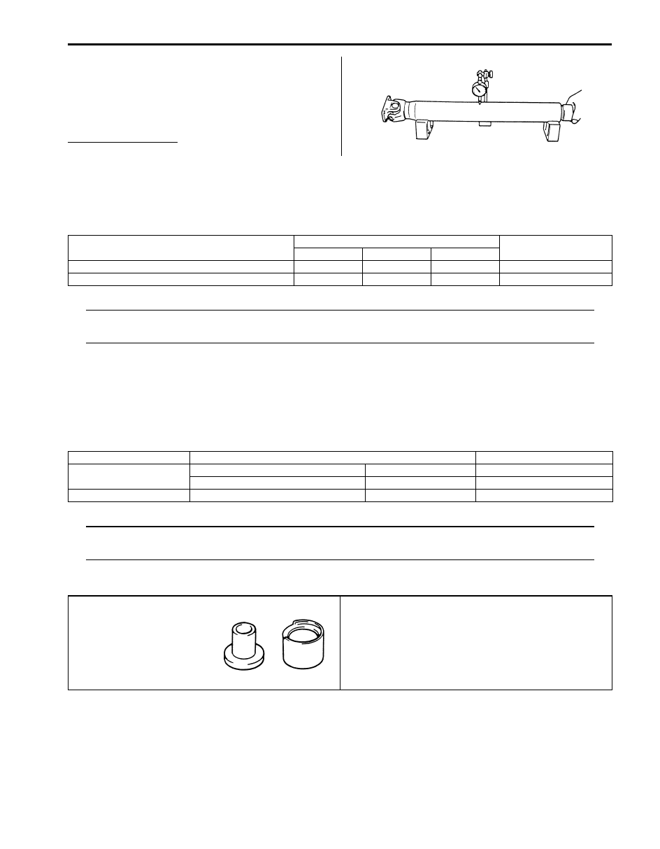
Inspect propeller shaft, universal joint and ball joint for
damage, and propeller shaft for runout.
If damage is found or shaft runout exceeds its limit,
replace.
Propeller shaft runout
Limit: 0.8 mm (0.031 in.)
Specifications
Tightening Torque Specifications
S6JB0B3407001
NOTE
The specified tightening torque is also described in the following.
“Propeller Shaft Construction”
Reference:
For the tightening torque of fastener not specified in this section, refer to “Fastener Information in Section 0A”.
Special Tools and Equipment
Recommended Service Material
S6JB0B3408001
NOTE
Required service material is also described in the following.
“Propeller Shaft Construction”
Special Tool
S6JB0B3408002
IYSQ01340013-01
Fastening part
Tightening torque
Note
N
⋅m
kgf-m
lb-ft
Front propeller shaft flange bolt
30
3.0
22.0
Rear propeller shaft flange nut
85
8.5
61.5
Material
SUZUKI recommended product or Specification
Note
Grease
SUZUKI Super Grease A
P/No.: 99000–25010
SUZUKI Super Grease C
P/No.: 99000–25030
Thread lock cement
Thread Lock Cement Super 1322
P/No.: 99000–32110
09926–48010
Universal joint assembling
tool
)
Нет комментариевНе стесняйтесь поделиться с нами вашим ценным мнением.
Текст