Suzuki Grand Vitara JB627. Manual — part 166
3C-68 Transfer:
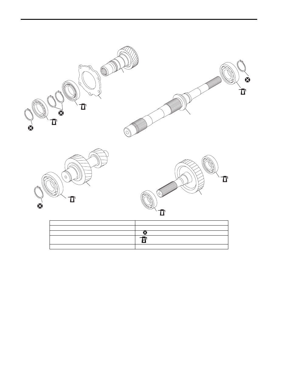
Input Gear Assembly, Counter Gear Assembly, Front Output Shaft Assembly and Rear Output Shaft
Assembly Components
S6JB0B3306011
4
3
2
5
6
7
OIL
2
OIL
2
OIL
2
OIL
2
OIL
1
1
1
1
2
OIL
I5JB0A331061-02
1. Snap ring
6. Counter gear
2. Bearing
7. Front output shaft
3. Input gear plate
: Do not reuse.
4. Input gear
: Apply transfer oil.
5. Rear output shaft
Transfer: 3C-69
Input Gear Assembly Disassembly and
Reassembly
S6JB0B3306012
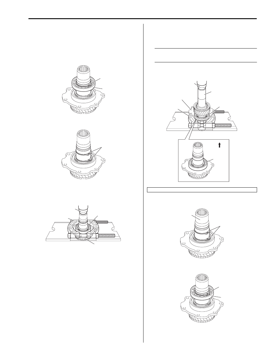
Disassembly
1) Remove snap ring (1) from input gear, and then
remove bearing (2).
2) Remove snap rings (1).
3) Remove bearing (1) from input gear (2) using
bearing puller (3) and press (4), and then remove
input gear plate.
Reassembly
1) Clean all components thoroughly, inspect them for
any abnormality and replace with new ones as
necessary.
2) Install input gear plate (1), and then press-fit bearing
(2) using special tool, bearing puller (3) and press
(4).
NOTE
Assemble bearing so that seal side (5) may
come to the front side.
Special tool
(A): 09913–85210
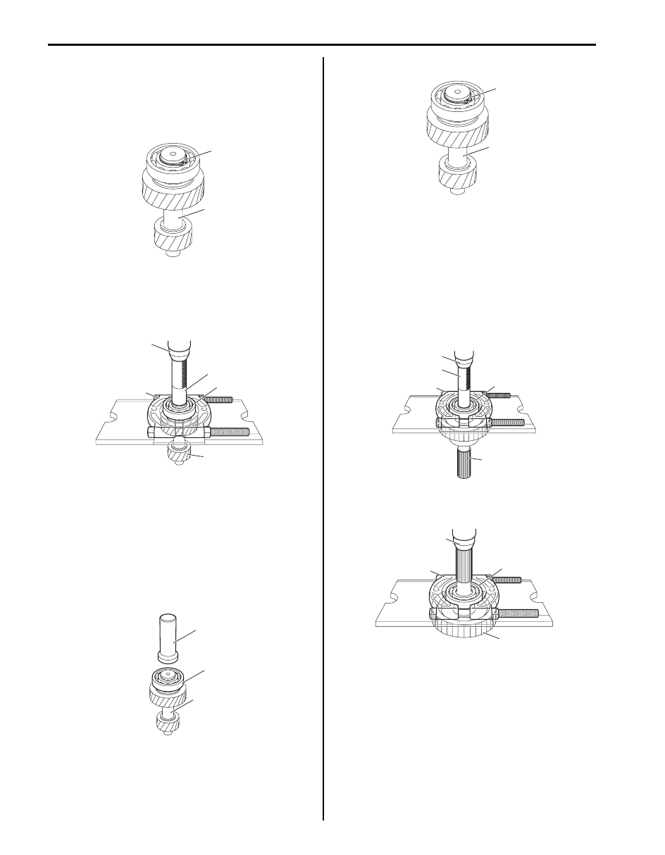
3) Install snap rings (1) to input gear (2).
4) Install bearing (1) and snap ring (2).
1
2
I5JB0A331062-01
1
I5JB0A331063-01
1
2
3
4
I5JB0A331064-01
[A]: Front side
(A)
2
3
1
4
5
[A]
I5JB0A331065-02
1
2
I5JB0A331066-01
2
1
I5JB0A331067-01
3C-70 Transfer:
Counter Gear Assembly Disassembly and
Reassembly
S6JB0B3306013
Disassembly
1) Remove snap ring (1) from counter gear (2).
2) Remove bearing (1) from counter gear (2) using
special tool, bearing puller (3) and press (4).
Special tool
(A): 09913–80113
Reassembly
1) Clean all components thoroughly, inspect them for
any abnormality and replace with new ones as
necessary.
2) Press-fit bearing (1) to counter gear using special
tool and press.
Special tool
(A): 09913–70123
3) Install snap ring (1) to counter gear (2).
Front Output Shaft Assembly Disassembly and
Reassembly
S6JB0B3306014
Disassembly
1) Remove bearing (1) from front output shaft (2) using
special tool, bearing puller (3) and press (4).
Special tool
(A): 09925–98221
2) Remove bearing (1) from front output shaft (2) using
bearing puller (3) and press (4).
1
2
I5JB0A331068-01
2
1
(A)
3
4
I5JB0A331069-02
(A)
1
2
I5JB0A331070-01
1
2
I5JB0A331068-01
1
2
(A)
4
3
I5JB0A331071-01
1
2
3
4
I5JB0A331072-01
Transfer: 3C-71
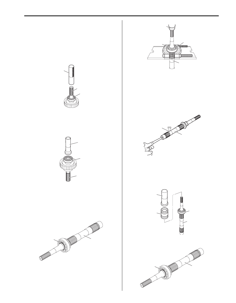
Reassembly
1) Clean all components thoroughly, inspect them for
any abnormality and replace with new ones as
necessary.
2) Press-fit bearing (1) to front output shaft using
special tool and press.
Special tool
(A): 09913–84510
3) Press-fit bearing (1) to front output shaft using
special tool and press.
Special tool
(A): 09913–76010
Rear Output Shaft Assembly Disassembly and
Reassembly
S6JB0B3306015
Disassembly
1) Remove snap ring (1) from rear output shaft (2).
2) Remove bearing (1) from rear output shaft (2) using
bearing puller (3) and press (4).
Reassembly
1) Clean all components thoroughly, inspect them for
any abnormality and replace with new ones as
necessary.
2) To ensure lubrication of rear output shaft (1), air blow
oil holes (2) and make sure that they are free from
any obstruction.
3) Press-fit bearing (1) to rear output shaft using
special tools and press.
Special tool
(A): 09913–85210
(B): 09940–54910
4) Install snap ring (1) to rear output shaft (2).
1
2
(A)
I5JB0A331073-01
(A)
1
2
I5JB0A331074-01
2
1
I5JB0A331075-01
1
3
4
2
I5JB0A331076-01
1
2
I5JB0A331077-01
1
2
(B)
(A)
I5JB0A331078-01
2
1
I5JB0A331075-01
Нет комментариевНе стесняйтесь поделиться с нами вашим ценным мнением.
Текст