Suzuki Grand Vitara JB627. Manual — part 167
3C-72 Transfer:
Specifications
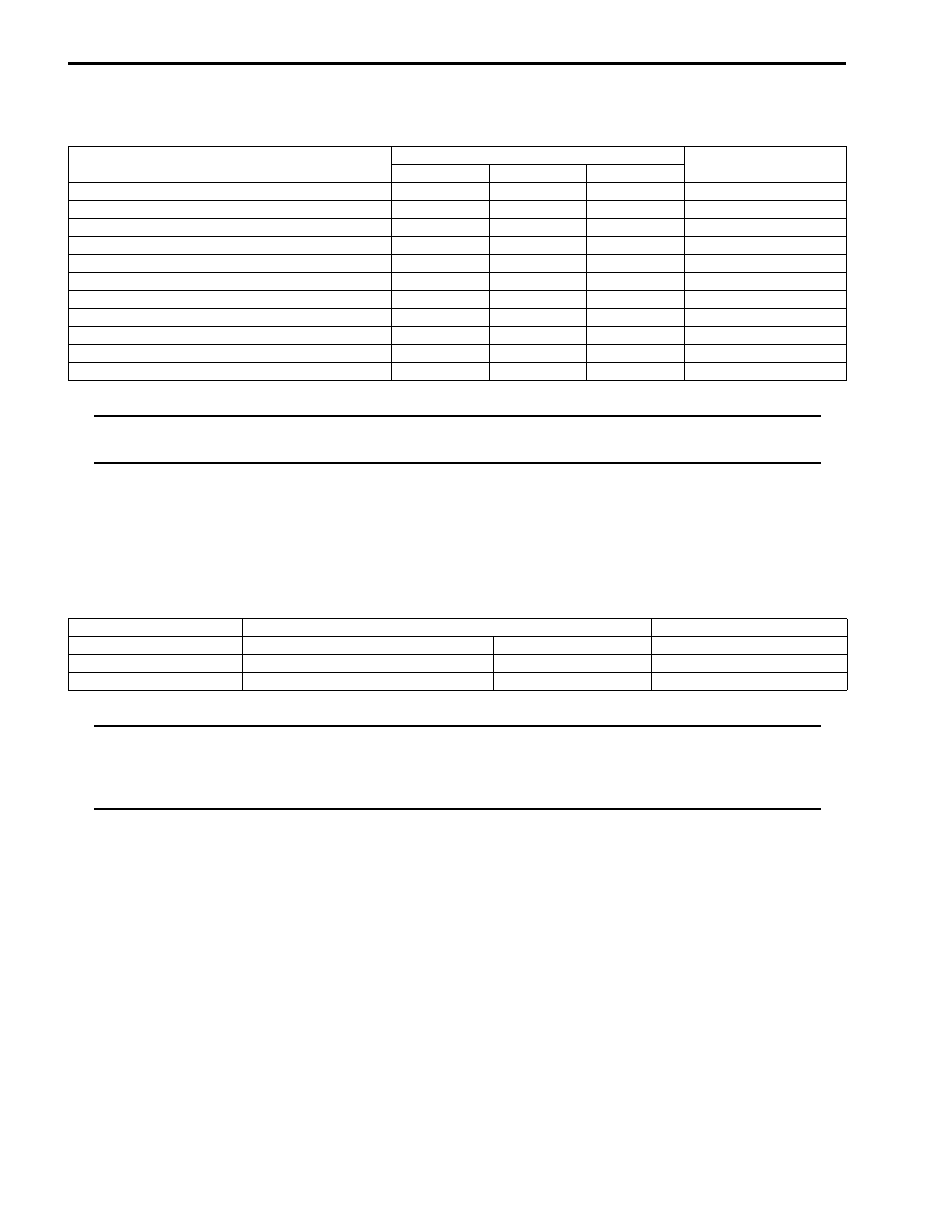
Tightening Torque Specifications
S6JB0B3307001
NOTE
The specified tightening torque is also described in the following.
“Transfer Assembly Components”
Reference:
For the tightening torque of fastener not specified in this section, refer to “Fastener Information in Section 0A”.
Special Tools and Equipment
Recommended Service Material
S6JB0B3308001
NOTE
Required service material is also described in the following.
“Transfer Assembly Components”
“Input Gear Assembly, Counter Gear Assembly, Front Output Shaft Assembly and Rear Output Shaft
Assembly Components”
Fastening part
Tightening torque
Note
N
⋅m
kgf-m
lb-ft
Transfer oil level / filler plug
23
2.3
17.0
Transfer oil drain plug
23
2.3
17.0
Input gear plate bolt
23
2.3
17.0
Rear case bolt
23
2.3
17.0
Strainer bolt
10
1.0
7.5
Oil pump cover bolt
23
2.3
17.0
Control cover bolt
23
2.3
17.0
Control cover dowel bolt
23
2.3
17.0
Center differential lock switch
20
2.0
14.5
4L/N switch
20
2.0
14.5
Harness bracket bolt
10
1.0
7.5
Material
SUZUKI recommended product or Specification
Note
Grease
SUZUKI Super Grease A
P/No.: 99000–25010
Sealant
SUZUKI Bond No.1217G
P/No.: 99000–31260
Thread lock cement
Thread Lock Cement Super 1322
P/No.: 99000–32110

Transfer: 3C-73
Special Tool
S6JB0B3308002
09912–34510
09913–70123
Case separator
Bearing installing tool
09913–76010
09913–80113
Bearing installer
Bearing installer
09913–84510
09913–85210
Bearing installer
Bearing installer
09925–98210
09925–98221
Input shaft bearing installer
Bearing installer
09928–36510
09940–54910
Transfer cap
Front fork oil seal install
driver
SUZUKI scan tool
—
This kit includes following
items. 1. Tech 2, 2. PCMCIA
card, 3. DLC cable, 4. SAE
16/19 adapter, 5. Cigarette
cable, 6. DLC loop back
adapter, 7. Battery power
cable, 8. RS232 cable, 9.
RS232 adapter, 10. RS232
loop back connector, 11.
Storage case, 12. ) / )

3D-1 Propeller Shaft:
Driveline / Axle
Propeller Shaft
Precautions
Propeller Shaft Caution
S6JB0B3400001
CAUTION
!
• All propeller shaft fasteners are an important attaching part in that it could affect the performance of
vital parts and systems, and/or could result in major repair expense. They must be replaced with one
of the same part number or with an equivalent part if replacement becomes necessary. Do not use a
replacement part of lesser quality or substitute design. Torque values must be used as specified
during reassembly to assure proper retention of this part.
• Never attempt to heat, quench or straighten any propeller shaft part. Replace it with a new part, or
damage to the part may result.
General Description
Propeller Shaft Construction
S6JB0B3401001
Most universal joints and ball joints require no maintenance. They are lubricated for life and can not be lubricated on
the vehicle. If a universal joint becomes noisy or worn, it must be replaced.
The propeller shaft is a balanced unit. Handle it carefully so that balance can be maintained.
I5JB0A340001-02
[A]: Front propeller shaft
4. Spider joint assembly
: Apply grease (99000-25030) to spider bearing race.
[B]: Rear propeller shaft
5. Circlip
1. Front propeller shaft flange bolt
: Apply thread lock 99000-32110 to bolt thread.
: 85 N
⋅m (8.5 kgf-m, 61.5 lb-ft)
2. Rear propeller shaft flange nut
: 30 N
⋅m (3.0 kgf-m, 22.0 lb-ft)
3. Support washer
: Do not reuse.
Propeller Shaft: 3D-2
Diagnostic Information and Procedures
Propeller Shaft Symptom Diagnosis
S6JB0B3404001
Repair Instructions
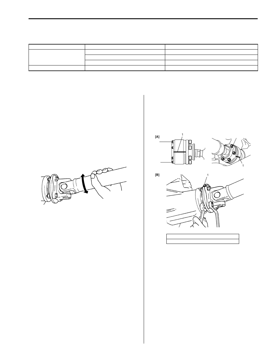
Propeller Shaft Joint Check
S6JB0B3406001
If universal joints and ball joints are suspected of
producing chattering or rattling noise, inspect them for
wear. For universal joint, check to see if cross spider
rattles in yokes or if splines are worn down and replace
defective propeller shaft assembly with new one.
Noise coming from universal joint and ball joint can be
easily distinguished from other noises because rhythm
of chattering or rattling is in step with cruising speed.
Noise is pronounced particularly on standing start or in
coasting condition (when braking effect of engine is
showing in the drive line).
Propeller Shaft Removal and Installation
S6JB0B3406002
Removal
1) Hoist vehicle.
2) Give match marks (1) on joint flange and propeller
shaft as shown in the figure.
3) Remove rear propeller shaft.
4) Drain transfer oil when removed front propeller shaft
from transfer.
Condition
Possible cause
Correction / Reference Item
Abnormal noise
Loose propeller shaft flange bolt and nut Tighten propeller shaft flange bolt and nut.
Spider bearing worn out or stuck
Replace.
Wear spider
Replace propeller shaft.
Vibration
Deformed propeller shaft
Replace.
I5JB0A340003-01
[A]: Front propeller shaft
[B]: Rear propeller shaft
I5JB0A340002-02
Нет комментариевНе стесняйтесь поделиться с нами вашим ценным мнением.
Текст