Suzuki Grand Vitara JB627. Manual — part 407
9M-1 Exterior Trim:
Body, Cab and Accessories
Exterior Trim
Repair Instructions
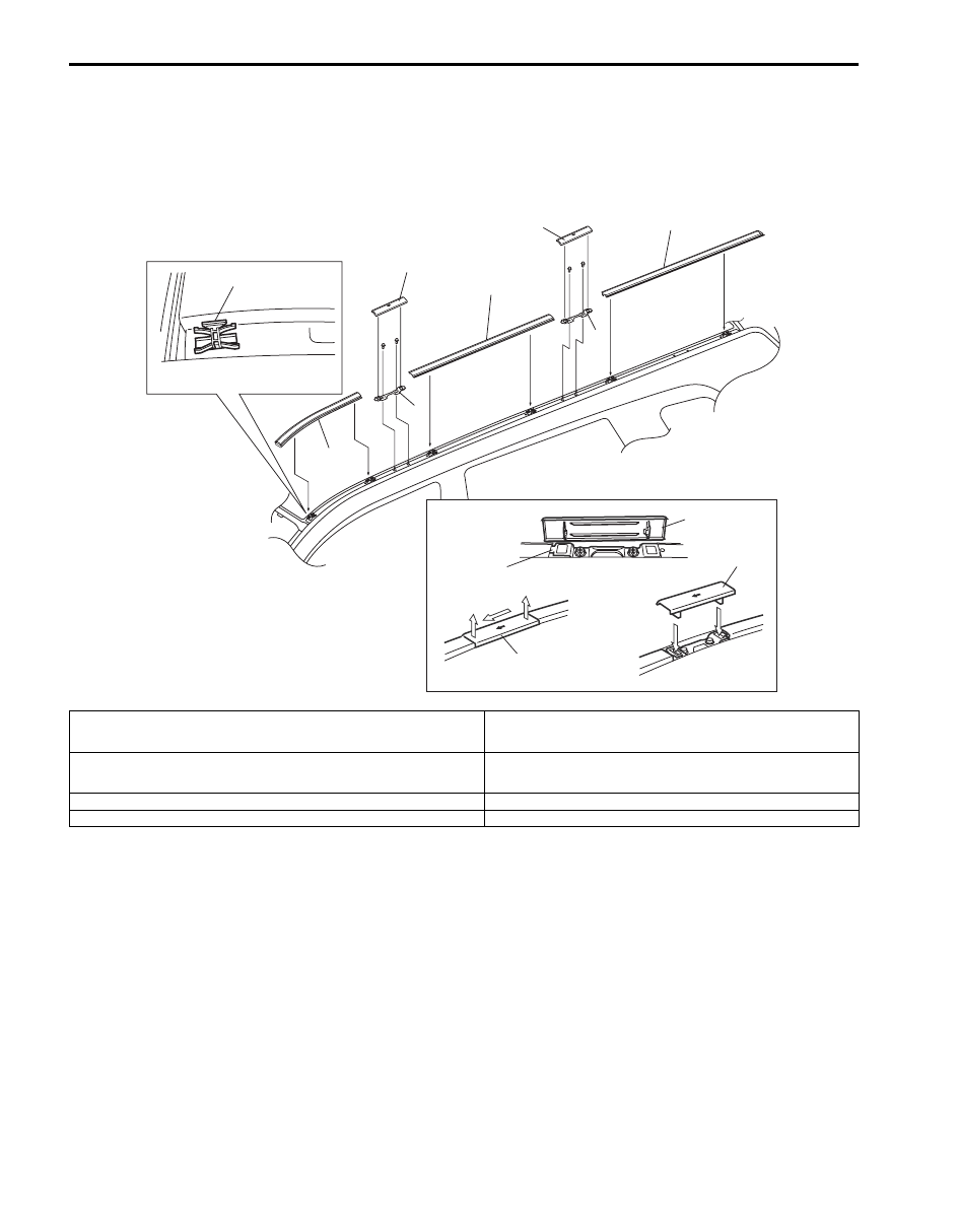
Roof Drip Molding Removal and Installation (If Equipped)
S6JB0B9D06001
1
3
2
4
4
6
5
5
[A]
[B]
a
a
b
b
c
5
5
5
4
I6JB019D0001-01
[A]: Molding Cap Removal
Remove cap by pushing in arrow direction shown on cap and then pulling in
alphabetical order indicated in figure.
3. Roof drip rear molding
[B]: Molding Cap Installation
Be sure to direct arrow mark of left side molding cap to vehicle forward and
arrow mark of right side molding cap to vehicle rearward.
4. Roof carrier bracket
1. Roof drip front molding
5. Roof drip molding cap
2. Roof drip center molding
6. Roof drip molding clip (Push-in type)
Exterior Trim: 9M-2
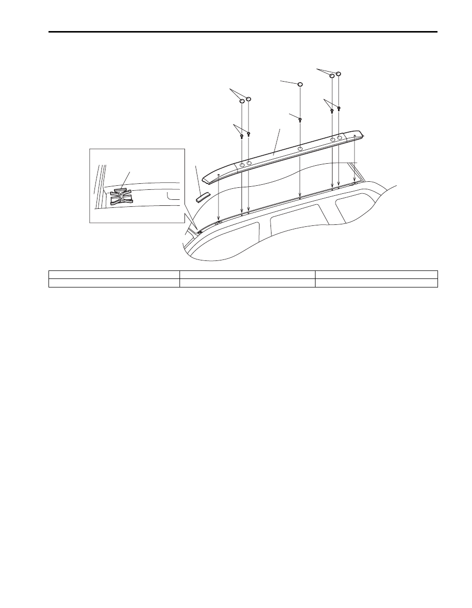
Roof Rail Removal and Installation (If Equipped)
S6JB0B9D06002
1
2
3
4
4
4
5
5
5
I6JB019D0002-01
1. Roof rail
3. Roof drip molding clip (Push-in type)
5. Roof rail bolt
2. Roof drip front molding
4. Roof rail cap
9M-3 Exterior Trim:
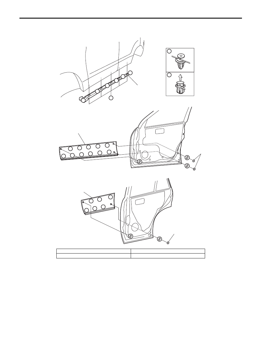
Splash Guard Removal and Installation (If Equipped)
S6JB0B9D06003
A
A
A
B
A
A
A
A
A
B
1
2
A
A
A
A
A
A
A
A
A
A
A
3
A
A
A
A
A
A
4
4
I6JB019D0003-01
1. Side sill splash guard
3. Rear door splash guard
2. Front door splash guard
4. Cap
Table of Contents 10- i
10
Section 10
CONTENTS
Control Systems
Precautions . . . . . . . . . . . ...10-1
Precautions. . . . . . . . . . . . . . ... 10-1
Precautions for Control Systems. . . . . . . 10-1
Cruise Control System. . . . . . .. 10A-1
Precautions. . . . . . . . . . . . . . .10A-1
Precautions in Diagnosing Troubles . . . . . 10A-1
General Description . . . . . . . . . . ...10A-2
Cruise Control System Construction . . . . . 10A-2
Components and Functions of Cruise Control
System . . . . . . . . . . . . . . . 10A-3
Schematic and Routing Diagram. . . . . ..10A-5
Cruise Control System Input / Output Diagram ..10A-5
Cruise Control System Wiring Diagram . . . 10A-6
Diagnostic Information and Procedures. . ..10A-7
Cruise Control System Check. . . . . . ... 10A-7
Customer Questionnaire (Example). . . . ..10A-8
DTC Check . . . . . . . . . . . . . ...10A-8
DTC Clearance . . . . . . . . . . . . . 10A-8
DTC Table. . . . . . . . . . . . . . .10A-9
Cruise Control System Symptom Diagnosis . .10A-9
DTC P0565: Cruise Control On Signal. . . 10A-10
DTC P0566 / P0567 / P0568: Cruise Control
Off Signal / Resume Signal / Set Signal . ... 10A-12
DTC P0571: Brake Switch Circuit . . . . ... 10A-13
Inspection of Cruise Control System Circuit. 10A-15
Repair Instructions . . . . . . . . . . ..10A-16
Cruise Control Switch Removal and
Installation. . . . . . . . . . . . . . 10A-16
Cruise Control Switch Inspection . . . . . 10A-16
CPP Switch (for Cruise Control) Removal and
Installation. . . . . . . . . . . . . . 10A-16
Clutch Pedal Position (CPP) Switch (for
Cruise Control) Inspection and Adjustment .. 10A-17
Specifications. . . . . . . . . . . . ...10A-17
Tightening Torque Specifications. . . . . 10A-17
Body Electrical Control System . . ... 10B-1
Precautions. . . . . . . . . . . . . . .10B-1
Precautions in Diagnosing Trouble . . . . ...10B-1
General Description . . . . . . . . . . ...10B-1
BCM General Description . . . . . . . . .10B-1
CAN Communication System Description. . .10B-2
Theft Deterrent Light Description . . . . . ..10B-3
Schematic and Routing Diagram. . . . . ..10B-4
Body Electrical Control System Wiring Circuit
Diagram. . . . . . . . . . . . . . ...10B-4
Connector Layout Diagram of BCM . . . . ..10B-5
Component Location . . . . . . . . . . .10B-6
BCM and Related System Component
Location. . . . . . . . . . . . . . ...10B-6
Diagnostic Information and Procedures. . ..10B-7
BCM Self-Diagnosis Function . . . . . . ...10B-7
Body Electrical Control System Check. . . ..10B-9
Scan Tool Data . . . . . . . . . . . ...10B-11
DTC Table. . . . . . . . . . . . . ...10B-13
DTC Check. . . . . . . . . . . . . ..10B-14
DTC Clearance . . . . . . . . . . . ...10B-15
BCM Power Circuit and Ground Circuit Check 10B-16
DTC B1133 (No. 1133): Battery Voltage Too
High. . . . . . . . . . . . . . . ...10B-17
DTC B1141 / B1142 (No. 1141 / No. 1142):
Outside Air Temperature (Ambient Temp.)
Sensor Circuit Malfunction . . . . . . . 10B-18
Communication Circuit Malfunction. . . ...10B-19
DTC B1157 (No. 1157): Air Bag Deployment
Signal Input . . . . . . . . . . . . ...10B-20
DTC B1170 (No. 1170): EEPROM access
error. . . . . . . . . . . . . . . ...10B-20
DTC U0155 (No. 0155): Lost Communication
with Instrument Panel Cluster (IPC) Control
Module . . . . . . . . . . . . . . ..10B-21
DTC U1073 (No. 1073): Control Module
Communication Bus Off . . . . . . . . 10B-23
DTC U1100 (No. 1100): Lost Communication
with ECM. . . . . . . . . . . . . ...10B-25
DTC U1101 (No. 1101): Lost communication
with TCM . . . . . . . . . . . . . ...10B-26
DTC U1144 (No. 1144): Lost Communication
with Keyless Start Control Module . . . . 10B-28
Нет комментариевНе стесняйтесь поделиться с нами вашим ценным мнением.
Текст