Suzuki Grand Vitara JB627. Manual — part 161

3C-48 Transfer:
DTC U1100: Lost Communication with ECM
S6JB0B3304027
Wiring Diagram
Refer to “DTC U1073: Control Module Communication Bus Off”.
DTC Detecting Condition and Trouble Area
DTC Confirmation Procedure
1) Clear DTC using scan tool.
2) Start engine and run it for 1 min. or more.
3) Stop vehicle and check DTC.
Troubleshooting
DTC detecting condition
Trouble area
Reception error of communication data for ECM is detected for
longer than specified time continuously.
• CAN communication circuit
• ABS or ESP
® hydraulic unit / control module
• ECM
• 4WD control module
Step
Action
Yes
No
1
Was “4WD control system check” performed?
Go to Step 2.
Go to “4WD Control
System Check”.
2
DTC check
1) Check DTC in 4WD control module.
Is DTC U1100 and DTC U1073 detected together?
Go to “DTC U1073:
Control Module
Communication Bus
Off”.
Go to Step 3.
3
DTC check
1) Check DTC in ECM.
Is DTC P1674 detected?
Go to “DTC U0073:
Control Module
Communication Bus Off
in Section 1A”.
Go to Step 4.
4
Check each control module connectors
1) Check connection of connectors of all control modules
communicating by means of CAN.
2) Recheck in 4WD control module.
Is DTC U1100 detected?
Go to Step 5.
NO Intermittent
trouble. Check for
intermittent referring to
“Intermittent and Poor
Connection Inspection
in Section 00”.
5
CAN communication circuit check
1) Turn ignition switch to OFF position.
2) Disconnect connectors of all control modules
communicating by means of CAN.
3) Check CAN communication circuit between control
modules for open, short and high resistance.
Is each CAN communication circuit in good condition?
Check ECM power and
ground circuit. If circuit
is OK, substitute a
known-good ECM and
recheck.
Repair circuit.

Transfer: 3C-49
DTC U1101: Lost Communication with TCM
S6JB0B3304028
Wiring Diagram
Refer to “DTC U1073: Control Module Communication Bus Off”.
DTC Detecting Condition and Trouble Area
DTC Confirmation Procedure
1) Clear DTC using scan tool.
2) Start engine and run it for 1 min. or more.
3) Stop vehicle and check DTC.
Troubleshooting
DTC detecting condition
Trouble area
Reception error of communication data for TCM is detected for
longer than specified time continuously.
• CAN communication circuit
• TCM
• 4WD control module
Step
Action
Yes
No
1
Was “4WD control system check” performed?
Go to Step 2.
Go to “4WD Control
System Check”.
2
DTC check
1) Check DTC in 4WD control module.
Is DTC U1100 and DTC U1073 detected together?
Go to “DTC U1073:
Control Module
Communication Bus
Off”.
Go to Step 3.
3
DTC check
1) Check DTC in TCM.
Is DTC P1774 detected?
Go to “DTC U0073:
Control Module
Communication Bus Off
in Section 5A”.
Go to Step 4.
4
Check each control module connectors
1) Check connection of connectors of all control modules
communicating by means of CAN.
2) Recheck in 4WD control module.
Is DTC U1100 detected?
Go to Step 5.
Intermittent trouble.
Check for intermittent
referring to “Intermittent
and Poor Connection
Inspection in Section
00”.
5
CAN communication circuit check
1) Turn ignition switch to OFF position.
2) Disconnect connectors of all control modules
communicating by means of CAN.
3) Check CAN communication circuit between control
modules for open, short and high resistance.
Is each CAN communication circuit in good condition?
Check TCM power and
ground circuit. If circuit
is OK, substitute a
known-good TCM and
recheck.
Repair circuit.

3C-50 Transfer:
DTC U1121: Lost Communication with ABS / Electronic Stability Program Hydraulic Unit / Control
Module
S6JB0B3304029
Wiring Diagram
Refer to “DTC U1073: Control Module Communication Bus Off”.
DTC Detecting Condition and Trouble Area
DTC Confirmation Procedure
1) Clear DTC using scan tool.
2) Start engine and run it for 1 min. or more.
3) Stop vehicle and check DTC.
Troubleshooting
Inspection of 4WD Control Module and Its Circuits
S6JB0B3304030
4WD control module and its circuits can be checked at coupler connected to 4WD control module by measuring
voltage, pulse signal.
CAUTION
!
4WD control module cannot be checked by itself. It is strictly prohibited to connect voltmeter or
ohmmeter to 4WD control module with couplers disconnected from it.
DTC detecting condition
Trouble area
Reception error of communication data for ABS or ESP
®
hydraulic unit / control module is detected for longer than
specified time continuously.
• CAN communication circuit
• ABS or ESP
® hydraulic unit / control module
• 4WD control module
Step
Action
Yes
No
1
Was “4WD control system check” performed?
Go to Step 2.
Go to “4WD Control
System Check”.
2
DTC check
1) Check DTC in 4WD control module.
Is DTC U1100 and DTC U1073 detected together?
Go to “DTC U1073:
Control Module
Communication Bus
Off”.
Go to Step 3.
3
DTC check
1) Check DTC in ABS or ESP
® hydraulic unit / control
module.
Is DTC PU1073 detected?
Go to “DTC U1073:
Control Module
Communication Bus Off
in Section 4E”.
Go to Step 4.
4
Check each control module connectors
1) Check connection of connectors of all control modules
communicating by means of CAN.
2) Recheck in 4WD control module.
Is DTC U1100 detected?
Go to Step 5.
Intermittent trouble.
Check for intermittent
referring to “Intermittent
and Poor Connection
Inspection in Section
00”.
5
CAN communication circuit check
1) Turn ignition switch to OFF position.
2) Disconnect connectors of all control modules
communicating by means of CAN.
3) Check CAN communication circuit between control
modules for open, short and high resistance.
Is each CAN communication circuit in good condition?
Check ABS or ESP
®
hydraulic unit / control
module power and
ground circuit. If circuit
is OK, substitute a
known-good ABS or
ESP
® hydraulic unit /
control module and
recheck.
Repair circuit.
Transfer: 3C-51
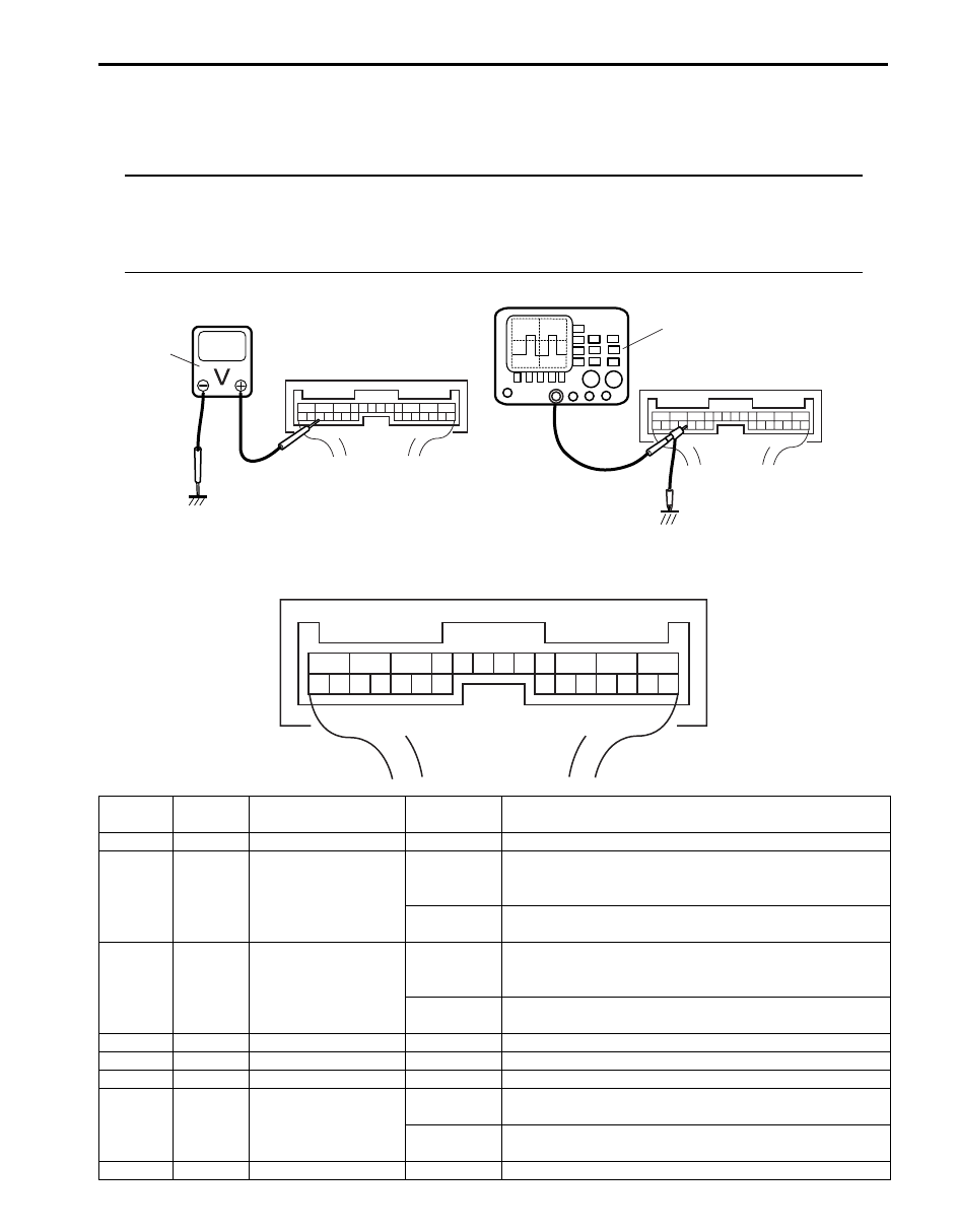
Voltage and Signal Check
1) Check voltage using voltmeter (1) connected to each terminal of couplers.
2) Check signal using oscilloscope (2) connected to each terminal of couplers.
NOTE
• As each terminal voltage is affected by the battery voltage, confirm that it is 11 V or more when
ignition switch is turned ON.
• Pulse signal cannot be measured by voltmeter. It can be measured by oscilloscope.
• Item with asterisk (*) in normal voltage column can be read only by oscilloscope.
Terminal arrangement of 4WD control module connector (Viewed from harness side)
1
2
I4JA01332053-01
1
2
3
4
5
6
7
8
9
10
11
12
13
14
15
16
17
18
19
20
21
22
23
24
25
26
I4JA01332054-01
Terminal
Number
Wire
Color
Circuit
Normal
Voltage
Condition
E91-1
BLK
Ground
0 – 1 V
—
E91-2
BLU
Transfer actuator
motor 1
10 – 14 V
Ignition switch turned to ON position and transfer shift
actuator being rotated N
→ 4H → 4H-lock direction or 4L-
lock
→ 4H-lock direction
0 – 1 V
Ignition switch turned to ON position and transfer shift
actuator in other than above-mentioned condition
E91-3
YEL
Transfer actuator
motor 2
10 – 14 V
Ignition switch turned to ON position and transfer shift
actuator being rotated 4H-lock
→ 4H → N direction or
4H-lock
→ 4L-lock direction
0 – 1 V
Ignition switch turned to ON position and transfer shift
actuator in other than above-mentioned condition
E91-4
—
—
—
—
E91-5
—
—
—
—
E91-6
—
—
—
—
E91-7
BLK/ORN Clutch switch
10 – 14 V
Ignition switch turned to ON position and clutch pedal
released
0 – 1 V
Ignition switch turned to ON position and clutch pedal
kept depressing
E91-8
PNK
Diagnosis switch
4 – 5 V
Ignition switch turned to ON position
Нет комментариевНе стесняйтесь поделиться с нами вашим ценным мнением.
Текст