Suzuki Grand Vitara JB627. Manual — part 193
4F-11 Electronic Stability Program:
Step 1: Malfunction Analysis
Customer complaint analysis
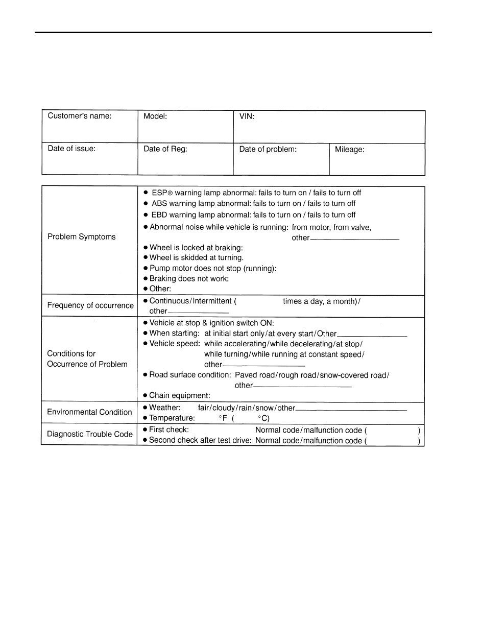
Record details of the problem (failure, complaint) and how it occurred as described by the customer.
For this purpose, use of such a questionnaire form as shown in the following will facilitate collecting information to the
point required for proper analysis and diagnosis.
Customer questionnaire (Example)
Problem symptom confirmation
If symptom in “Customer Questionnaire” is found or reproduced in the vehicle, confirm the symptom is problem or not.
(This step should be done with the customer if possible.) Check warning lights related to brake system referring to
“EBD Warning Light (Brake Warning Light) Comes ON Steady in Section 4E”, “ABS Warning Light Check in Section
4E” and “ESP
I6JB01460011-02
Electronic Stability Program: 4F-12
DTC check, record and clearance
Perform “DTC Check” procedure, record it and then clear it referring to “DTC Clearance”.
Recheck DTC referring to “DTC Check”.
When DTC which is recorded at DTC check procedure is detected again after performing DTC clearance, go to “Step
4: ESP
® Check: ” to proceed the diagnosis.
When DTC which is recorded at DTC check procedure is not indicated anymore after performing DTC clearance,
ESP
® control module does not perform the system diagnosis, or temporary abnormality may occur, therefore go to
“Step 2: Driving Test: ” to proceed the diagnosis.
Step 2: Driving Test
Test the vehicle at 40 km/h for more than a minute including left and right turns and check if any trouble symptom
(such as ESP
® warning light and/or ABS warning light) exists.
If the malfunction DTC is confirmed at ignition switch ON, proceed to Step 3.
If the malfunction DTC is not confirmed at ignition switch ON, proceed to Step 6.
Step 3: DTC Check
Recheck DTC referring to “DTC Check”.
Step 4: ESP
® Check
According to ESP
® Check for the DTC confirmation in Step 3, locate the cause of the trouble, namely in a sensor,
switch, wire harness, connector, actuator assembly or other part and repair or replace faulty parts.
Step 5: Brakes Diagnosis
Check the parts or system suspected as a possible cause referring to “Brakes Symptom Diagnosis in Section 4A” and
based on symptoms appearing on the vehicle (symptom obtained through Steps 1 and 2 and repair or replace faulty
parts, if any).
Step 6: Check for Intermittent Problem
Check parts where an intermittent trouble is easy to occur (e.g., wire harness, connector, etc.), referring to
“Intermittent and Poor Connection Inspection in Section 00” and related circuit of trouble code recorded in Step 1 to 3.
Step 7: Final Confirmation Test
Confirm that the problem symptom has gone and the ESP
® is free from any abnormal conditions. If what has been
repaired is related to the malfunction DTC, clear the DTC once referring to “DTC Clearance” and perform test driving
and confirm that no DTC is indicated.
ESP
® Warning Light Check
S6JB0B4604022
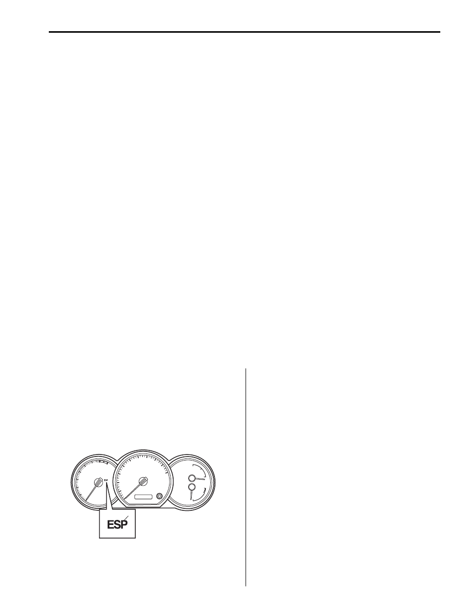
1) Turn ignition switch ON.
2) Check that ESP
® warning light (1) comes ON for
about 2 seconds and then goes off.
If any faulty condition is found, advance to “ESP
Warning Light Does Not Come ON at Ignition Switch
ON” or “ESP
® Warning Light Comes ON Steady”.
ABS Warning Light Check
S6JB0B4604002
Refer to “ABS Warning Light Check in Section 4E”.
EBD Warning Light (Brake Warning Light)
Check
S6JB0B4604003
Refer to “EBD Warning Light (Brake Warning Light)
Check in Section 4E”.
1
I6JB01460012-01
4F-13 Electronic Stability Program:
DTC Check
S6JB0B4604004
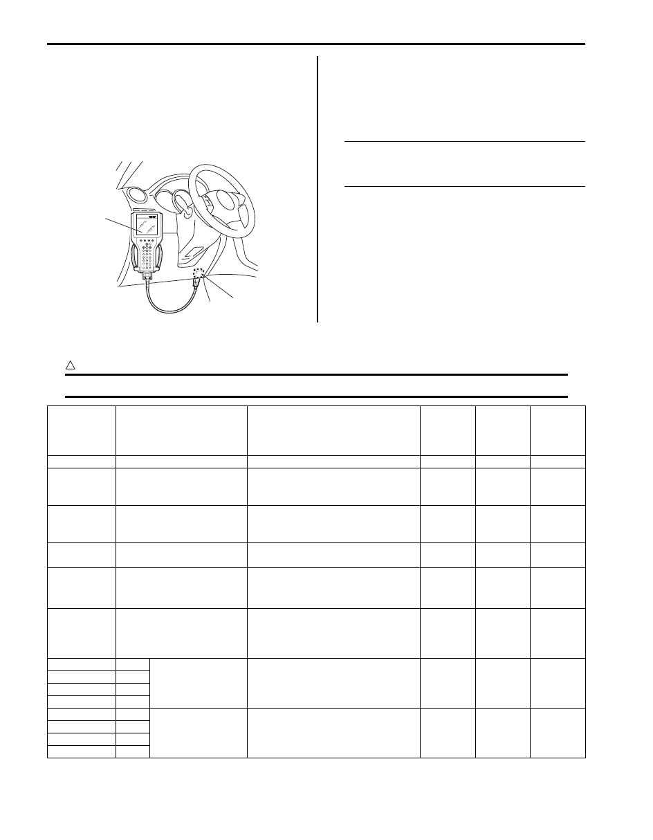
1) Turn ignition switch to OFF position.
2) Connect SUZUKI scan tool to data link connector
(1).
Special tool
(A): SUZUKI scan tool
3) Turn ignition switch to ON position.
4) Read DTC according to instructions displayed on
SUZUKI scan tool and print it or write it down. Refer
to SUZUKI scan tool operator’s manual for further
details.
NOTE
If SUZUKI scan tool can not communicate
ESP
® control module, perform “Serial Data
5) After completing the check, turn ignition switch off
and disconnect SUZUKI scan tool from DLC.
DTC Table
S6JB0B4604005
CAUTION
!
Be sure to perform “Electronic Stability Program Check” before starting diagnosis.
(A)
1
I5JB0A450008-01
DTC
(displayed
on SUZUKI
scan tool)
Diagnostic Items
Detecting condition (DTC will be
set when detecting)
ABS
warning
light
EBD
warning
light
ESP
®
warning
light
NO DTC
Normal
—
—
—
—
C1015
Longitudinal G sensor in
yaw rate / G sensor
assembly failure
Longitudinal G sensor signal is out of
specified range. (4WD model)
{
—
{
C1016
Brake light switch failure
Vehicle behavior and brake light
switch signal is disagreed for
specified time.
—
—
—
C1017
Lateral G sensor in yaw rate
/ G sensor assembly failure
Lateral G sensor signal is out of
specified range.
—
—
{
C1018
Brake fluid level switch
failure
• Brake fluid level is too low.
• Input voltage of brake fluid level
switch to BCM is low.
—
—
{
C1020
Master cylinder pressure
sensor power supply failure
Power supply voltage to master
cylinder pressure sensor in ESP
®
hydraulic unit / control module
assembly is too low.
—
—
{
C1021
RF
Wheel speed
sensor circuit failure
Wheel sensor signal is out of
specified range.
{
*1
{
C1025
LF
C1031
RR
C1035
LR
C1022
RF
Wheel speed
sensor or encoder
failure
Abnormal wheel speed sensor signal
is detected.
{
*1
{
C1026
LF
C1032
RR
C1036
LR
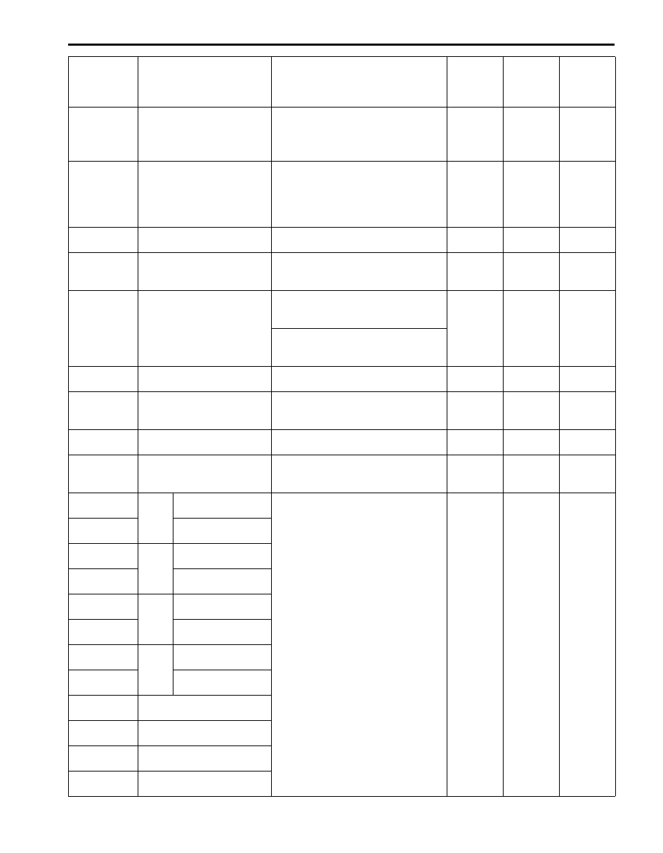
Electronic Stability Program: 4F-14
Yaw rate sensor in yaw rate
/ G sensor assembly failure
• Yaw rate sensor signal is out of
range.
• Vehicle behavior and yaw rate
signal is disagreed.
—
—
{
Steering angle sensor
circuit failure
• Steering angle sensor internal
defect is detected by CPU in
steering angle sensor.
• Steering angle sensor signal is out
of specified range.
—
—
{
ESP
® OFF switch circuit
failure
Mechanical switch failure, failure in
switch wiring is shorted to ground.
—
—
—
Master cylinder pressure
sensor circuit failure
Input signal voltage from master
cylinder pressure sensor in ESP
®
control module is too high or low.
—
—
{
Yaw rate / G sensor
assembly power supply
failure
Power supply voltage of yaw rate / G
sensor assembly is too high when
ignition switch OFF.
—
—
{
Power supply voltage of yaw rate / G
sensor assembly is too low when
ignition switch ON.
Steering angle sensor
power supply failure
Power supply voltage to steering
angle sensor is too low.
—
—
{
Steering angle sensor
detect rolling counter failure
from ESP
® control module
ESP
® control module rolling counter
failure is detected by steering angle
sensor.
—
—
{
Yaw rate / G sensor
assembly internal failure
Yaw rate / G sensor assembly
internal failure is detected.
—
—
{
Stability control system
function failure
Stability control is active for more
than specified time without yaw rate
change.
—
—
{
RF
Inlet solenoid valve
circuit failure
Mismatching solenoid output and
solenoid monitor is detected.
{
{
{
Outlet solenoid
valve circuit failure
LF
Inlet solenoid valve
circuit failure
Outlet solenoid
valve circuit failure
RR
Inlet solenoid valve
circuit failure
Outlet solenoid
valve circuit failure
LR
Inlet solenoid valve
circuit failure
Outlet solenoid
valve circuit failure
Master cylinder cut solenoid
valve circuit No.1 failure
Master cylinder cut solenoid
valve circuit No.2 failure
Low pressure solenoid
valve circuit No.1 failure
Low pressure solenoid
valve circuit No.2 failure
DTC
(displayed
on SUZUKI
scan tool)
Diagnostic Items
Detecting condition (DTC will be
set when detecting)
ABS
warning
light
EBD
warning
light
ESP
®
warning
light
Нет комментариевНе стесняйтесь поделиться с нами вашим ценным мнением.
Текст