Suzuki Grand Vitara JB627. Manual — part 380
9C-13 Instrumentation / Driver Info. / Horn:
Clock Symptom Diagnosis (If Equipped)
S6JB0B9304019
Display does not change
at 50
°
C
Outside air temperature is 50
°C (122
°F) or more
—
Outside air temperature sensor faulty
Check outside air temperature sensor referring
to “Outside Air Temperature Sensor Inspection
(If Equipped)”.
Information display unit faulty
Replace unit.
BCM faulty
Replace after making sure that none of above
parts is faulty.
Display of thermometer
does not change at “- - -
°
C”
Outside air temperature sensor faulty
Check outside air temperature sensor referring
to “Outside Air Temperature Sensor Inspection
(If Equipped)”.
Outside air temperature sensor circuit is
open or short
Repair circuit.
Wiring or grounding faulty
Repair circuit.
Information display unit faulty
Replace unit.
BCM faulty
Replace after making sure that none of above
parts is faulty.
Display of fuel
consumption does not
change at “- - - l / 100 km
(km/l, MPG)”
Vehicle is not running (instantaneous
fuel consumption mode)
—
Fuel consumption was reset (average
fuel consumption mode, if equipped)
Vehicle runs for a while.
Vehicle speed signal faulty
Check ECM for DTC referring to “DTC Check
in Section 1A”
Wiring or grounding faulty
Repair circuit.
ECM faulty
Check input and output signal of ECM referring
to “Inspection of ECM and Its Circuits in
Section 1A”
Information display unit faulty
Replace unit.
BCM faulty
Replace after making sure that none of above
parts is faulty.
Condition
Possible cause
Correction / Reference Item
Condition
Possible cause
Correction / Reference Item
No displaying of clock
Circuit fuse Blown
Replace fuse and check for short circuit.
Wiring and/or grounding faulty
Repair as necessary.
Clock unit faulty
Replace unit.
Instrumentation / Driver Info. / Horn: 9C-14
Audio System Symptom Diagnosis (If Equipped)
S6JB0B9304020
Radio
NOTE
Electronic part / system with undiagnosed problem may cause electromagnetic interference.
Electromagnetic interference condition may have poor radio reception. To test for presence of
electromagnetic interference in part / system, perform the following procedures.
1. Turn ignition switch to OFF.
2. Systematically disconnect the electronic part / system connector(s) one at a time.
3. Turn ignition switch to ON.
4. Check any improvement in radio reception.
CD Player
Condition
Possible cause
Correction / Reference Item
Poor radio reception
Out of service area (Poor location)
—
Antenna faulty
Replace antenna.
Antenna amplifier faulty
Replace antenna amplifier.
Electrical part / system faulty
Repair or replace electrical part / system
referring to after-mentioned NOTE.
Wiring and/or grounding faulty
Repair as necessary.
Radio assembly faulty
Replace radio assembly.
Radio does not operate
and speaker does not
sound
Circuit fuse(s) blown
Replace fuse(s) and check for short circuit.
Wiring and/or grounding faulty
Repair as necessary.
Radio assembly faulty
Replace radio assembly.
Radio does not operate,
but speaker sound
Wiring and/or grounding faulty
Repair as necessary.
Radio assembly faulty
Replace radio assembly.
Radio is operative, but all
speakers does not sound
Wiring and/or grounding faulty
Repair as necessary.
Radio assembly faulty
Replace radio assembly.
Individual speaker is
noisy or inoperative
Wiring and/or grounding faulty
Repair as necessary.
Speaker faulty
Replace speaker.
Radio assembly faulty
Replace radio assembly.
Sound quality is poor
Out of service area (Poor location)
—
Speaker installed incorrectly
Install correctly.
Wiring and/or grounding faulty
Repair as necessary.
Speaker faulty
Replace speaker.
Radio assembly faulty
Replace radio assembly.
Condition
Possible cause
Correction / Reference Item
CD-ROM does not insert
Another CD-ROM already inserted
Eject CD-ROM.
Circuit fuse blown
Replace fuse and check for short circuit.
Wiring and/or grounding faulty
Repair as necessary.
Extraneous material come to be mixed
CD player
Clear extraneous material from CD player or
replace radio assembly.
Radio assembly faulty
Replace radio assembly.
CD-ROM does not eject
Circuit fuse blown
Replace fuse and check for short circuit.
Wiring and/or grounding faulty
Repair as necessary.
Extraneous material come to be mixed
in CD player
Clear extraneous material from CD player or
replace radio assembly.
Radio assembly faulty
Replace radio assembly.
CD player does not load
CD-ROM
CD-ROM faulty
—
CD-ROM inserted with incorrect side up Insert correctly.
Temperature in cabin is too hot
—
Water droplets form on internal lens
Dry about 1 hour with power on.
Radio assembly faulty
Replace radio assembly.
9C-15 Instrumentation / Driver Info. / Horn:
Auto Volume Control System
Remote Audio Control Switch Symptom Diagnosis (If Equipped)
S6JB0B9304021
Navigation Symptom Diagnosis (If Equipped)
S6JB0B9304022
Sound skips or is noisy
CD-ROM faulty
—
Driving vibration
—
Water droplets form on internal lens
Dry about 1 hour with power on.
Radio assembly installed incorrectly
Install correctly.
Radio assembly faulty
Replace radio assembly.
CD player is operative,
but all speakers does not
sound
Wiring and/or grounding faulty
Repair as necessary.
Radio assembly faulty
Replace radio assembly.
Individual speaker is
noisy or inoperative
Wiring and/or grounding faulty
Repair as necessary.
Speaker faulty
Replace speaker.
Radio assembly faulty
Replace radio assembly.
Sound quality or volume
is poor
CD-ROM faulty
—
Wiring and/or grounding faulty
Repair as necessary.
Speaker installed incorrectly
Install correctly.
Speaker faulty
Replace speaker.
Condition
Possible cause
Correction / Reference Item
Condition
Possible cause
Correction / Reference Item
Sound volume does not
vary according to
changes of vehicle speed
Auto volume control system is “OFF”
mode
Select auto volume control.
Vehicle speed signal faulty
Check vehicle speed signal referring to
“Vehicle Speed Signal Inspection (For Audio
Unit) (If Equipped)”.
Wiring or grounding faulty
Repair circuit.
BCM faulty
Check input and output signal of BCM referring
to “Inspection of BCM and Its Circuits in
Section 10B”.
Radio assembly faulty
Replace radio assembly.
Condition
Possible cause
Correction / Reference Item
Audio system is
operative, but remote
control switch does not
control audio system
Remote audio control switch faulty
Check remote audio control switch referring to
“Remote Audio Control Switch Inspection (If
Equipped)”.
Contact coil faulty
Replace contact coil.
Wiring and/or grounding faulty
Repair as necessary.
Radio assembly faulty
Replace radio assembly.
Condition
Possible cause
Correction / Reference Item
No displaying of
navigation
Circuit fuse Blown
Replace fuse and check for short circuit.
Wiring and/or grounding faulty
Repair circuit.
Navigation unit faulty
Replace unit.
Instrumentation / Driver Info. / Horn: 9C-16
Repair Instructions
Ignition Switch Removal and Installation
S6JB0B9306001
Removal
1) Disconnect negative cable at battery.
2) Confirm that ignition key is removed.
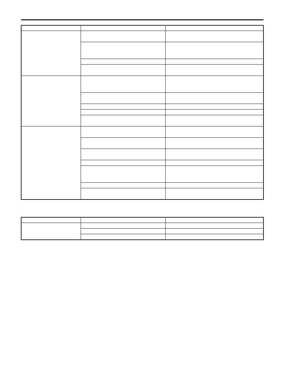
3) Remove steering column hole cover (1).
4) Turn steering wheel to remove steering column
cover screws (3) and then remove steering column
covers (2).
5) Disconnect couplers (1) from ignition switch (2).
6) Remove ignition switch (2) from key cylinder (3).
Installation
Reverse removal procedure.
Ignition Switch Inspection
S6JB0B9306002
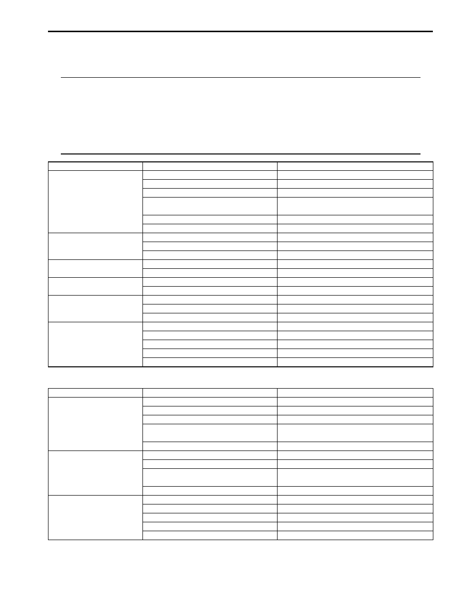
• Check for continuity between terminals at each switch
position. If check result is not as specified, replace
switch.
1
2
3
3
I5JB0A940020-02
1
1
2
3
I4RS0A930008-01
Position
Terminal
LOCK
ACC
ON
START
OUT
IN
K2
K1
ST
IG2
IG1
ACC
B1
B2
Ignition knob switch
(with keyless start system only)
ACC
IG1
IG2
ST
B2
B1
K2
K1
P2
P1
Terminal
OFF (ignition knob switch released)
ON (ignition knob switch pushsed)
P1
P2
Key
I5RS0D930003-02
Нет комментариевНе стесняйтесь поделиться с нами вашим ценным мнением.
Текст