Suzuki Grand Vitara JB627. Manual — part 72
1A-237 Engine General Information and Diagnosis:
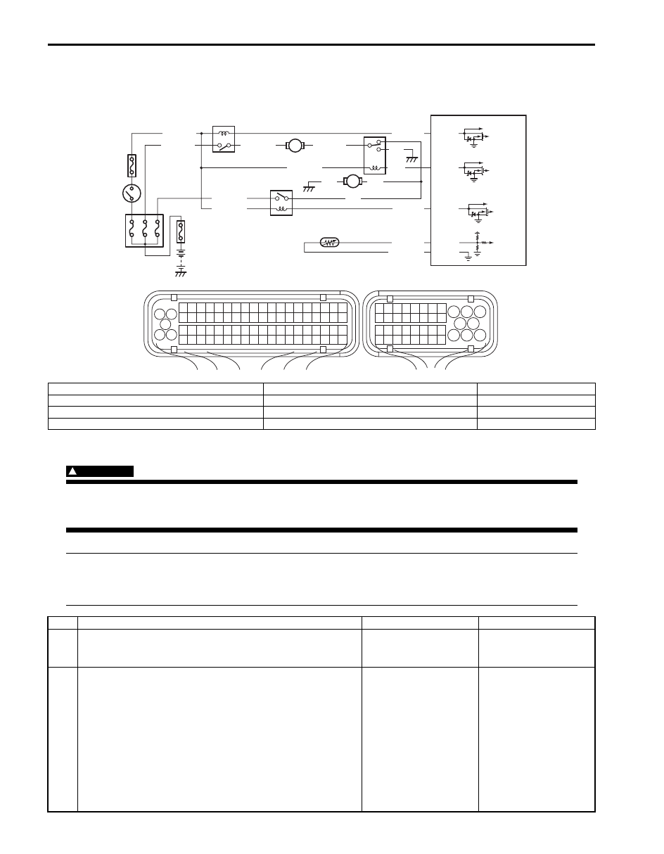
Radiator Cooling Fan Low Speed Control System Check
S6JB0B1104091
Wiring Diagram
Troubleshooting
WARNING
!
Keep hands, tools, and clothing away from engine cooling fan to help prevent personal injury. This fan
is electric and can come on whether or not the engine is running. The fan can start automatically in
response to the ECT sensor with the ignition switch at the “ON” position.
NOTE
• Before performed troubleshooting, be sure to read the “Precautions of ECM Circuit Inspection”.
• When measuring circuit voltage, resistance and/or pulse signal at ECM connector, connect the
special tool to ECM and/or the ECM connectors referring to “Inspection of ECM and Its Circuits”.
1
3 2
4
5
6
7
8
9
1110
12
13
14
15
16
17
18
19
20
17
18
19
20
21
22
23
24
25
26
27
28
29
30
31
33
34
35
36
37
38
39
40
32
1
2
3
4
5
6
7
8
9
10
11
12
13
14
15
16
21
22
23
24
25
26
27
28
29
30
31
32
33
34
35
36
37
38
39
40
41
42
43
44
45
46
47
48
49
50
51
52
53
54
55
56
57
58
59
60
61
62
63
64
65
66
67
68
69
70
71
72
73
74
75
76
77
78
79
80
81
E23
C37
BLU/BLK
BLK
RED
YEL/GRN
RED/YEL
BLK
BLU
BLU
BLU/WHT
YEL/GRN
E23-37
E23-15
E23-23
E23-14
YEL/GRN
BLU/RED
BLU/YEL
RED/BLK
5V
C37-26
C37-67
PPL/YEL
GRY/GRN
3
6
5
9
7
8
4
10
2
1
I6JB01110015-02
1. Fuse box No.1
5. Radiator cooling fan relay No.3
9. ECT sensor
2. Ignition switch
6. Radiator cooling fan motor No.1
10. “IG2 SIG” fuse
3. Radiator cooling fan relay No.1
7. Radiator cooling fan motor No.2
4. Radiator cooling fan relay No.2
8. ECM
Step
Action
Yes
No
1
Is there DTC(s) of ECT sensor circuit (DTC P0116 / P0117 /
P0118) and/or radiator cooling fan circuit (DTC P0480 /
P0481 / P0482)?
Go to corresponding
DTC flow.
Go to Step 2.
2
Low speed radiator cooling fan control circuit check
1) Connect scan tool to DLC with ignition switch turned
OFF.
2) Start engine and select “DATA LIST” mode on scan tool.
3) Warm up engine until coolant temp. is 92
°C (197.6 °F)
or higher and A/C switch turns OFF (if equipped with A/
C). (If engine coolant temp. dose not rise, check engine
cooling system or ECT sensor.)
Is radiator cooling fan started at low speed when engine
coolant temp. reached above temp.?
Radiator cooling fan low
speed control system is
in good condition.
Perform from Step 2 to
Step of “DTC P0480 /
P0481 / P0482: Fan 1 /
Fan 2 / Fan 3 Control
Circuit”.

Engine General Information and Diagnosis: 1A-238
3
Wire circuit check
1) Disconnect radiator cooling fan relay No.1 from relay
box with ignition switch turned OFF.
2) Turn ON ignition switch.
3) Measure voltage between “BLU/WHT” wire terminal of
radiator cooling fan relay No.1 connector and vehicle
body ground.
Is voltage 10 – 14 V?
Go to Step 4.
“BLU/WHT” wire is open
circuit.
4
Radiator cooling fan control check
1) Disconnect connector from radiator cooling fan motor
No.1 and connect radiator cooling fan relay No.1 with
ignition switch turned OFF.
2) Run engine until ECT is over 92
°C (197.6 °F).
3) Measure voltage between “BLU/RED” wire terminals of
radiator cooling fan motor No.1 connector and vehicle
body ground.
Is voltage 10 – 14 V?
Go to Step 5.
Go to Step 6.
5
Wire circuit check
1) Disconnect radiator cooling fan relay No.1 from relay
box with ignition switch turned OFF.
2) Measure resistance between “BLU/RED” wire terminals
of radiator cooling fan relay No.1 connector and radiator
cooling fan motor No.1 connector.
Is resistance below 3
Ω
?
Go to Step 15.
“BLU/RED” wire is open
or high resistance.
6
Wire circuit check
1) Disconnect radiator cooling fan relay No.2 and connect
radiator cooling fan motor No.1 connector with ignition
switch turned OFF.
2) Run engine until ECT is over 92
°C (197.6 °F).
3) Measure voltage between “BLU/YEL” wire terminal of
radiator cooling fan relay No.2 connector and vehicle
body ground.
Is voltage 10 – 14 V?
Go to Step 10.
Go to Step 7.
7
Wire circuit check
1) Disconnect radiator cooling fan motor No.1 connector
with ignition switch turned OFF.
2) Measure resistance between “BLU/YEL” wire terminal of
radiator cooling fan relay No.2 connector and vehicle
body ground.
Is resistance infinity?
Go to Step 8.
“BLU/YEL” wire is
shorted to ground
circuit.
8
Wire circuit check
1) Measure voltage between “BLU/YEL” wire terminal of
radiator cooling fan relay No.2 connector and vehicle
body ground with ignition switch turned ON.
Is voltage 0 V?
Go to Step 9.
“BLU/YEL” wire is
shorted to other circuit.
Step
Action
Yes
No

1A-239 Engine General Information and Diagnosis:
9
Wire circuit check
1) Measure resistance between “BLU/YEL” wire terminal of
radiator cooling fan relay No.2 connector and radiator
cooling fan motor No.1 connector with ignition switch
turned OFF.
Is resistance below 5
Ω
?
Go to Step 16.
“BLU/YEL” wire is open
circuit.
10 Radiator cooling fan control check
1) Disconnect connector from radiator cooling fan motor
No.2 and connect radiator cooling fan relay No.2 with
ignition switch turned OFF.
2) Run engine until ECT is over 92
°C (197.6 °F).
3) Measure voltage between “BLU” wire terminals of
radiator cooling fan motor No.2 connector and vehicle
body ground.
Is voltage 10 – 14 V?
Go to Step 14.
Go to Step 11.
11 Wire circuit check
1) Disconnect radiator cooling fan relay No.2 with ignition
switch turned OFF.
2) Measure resistance between “BLU” wire terminal of
radiator cooling fan relay No.2 connector and vehicle
body ground.
Is resistance infinity?
Go to Step 12.
“BLU” wire is shorted to
ground circuit.
12 Wire circuit check
1) Measure voltage between “BLU” wire terminal of radiator
cooling fan relay No.2 connector and vehicle body
ground with ignition switch turned ON.
Is voltage 0 V?
Go to Step 13.
“BLU” wire is shorted to
other circuit.
13 Wire circuit check
1) Measure resistance between “BLU” wire terminals of
radiator cooling fan relay No.2 connector and radiator
cooling fan motor No.2 connector with ignition switch
turned OFF.
Is resistance below 3
Ω
?
Go to Step 15.
“BLU” wire is open
circuit.
14 Wire circuit check
1) Measure resistance between “BLK” wire terminal of
radiator cooling fan motor No.2 connector and vehicle
body ground with ignition switch turned OFF.
Is resistance below 3
Ω
?
Go to Step 16.
“BLK” wire is open
circuit.
15 Radiator cooling fan motor check
1) Check radiator cooling fan motor referring to “Radiator
Cooling Fan Motor On-Vehicle Inspection in Section 1F”.
Is it in good condition?
Substitute a known
good ECM and recheck.
Replace radiator cooling
fan motor.
16 Radiator cooling fan motor check
1) Check radiator cooling fan motor referring to “Radiator
Cooling Fan Motor On-Vehicle Inspection in Section 1F”.
Is it in good condition?
Substitute a known
good ECM and recheck.
Replace radiator cooling
fan motor.
Step
Action
Yes
No
Engine General Information and Diagnosis: 1A-240
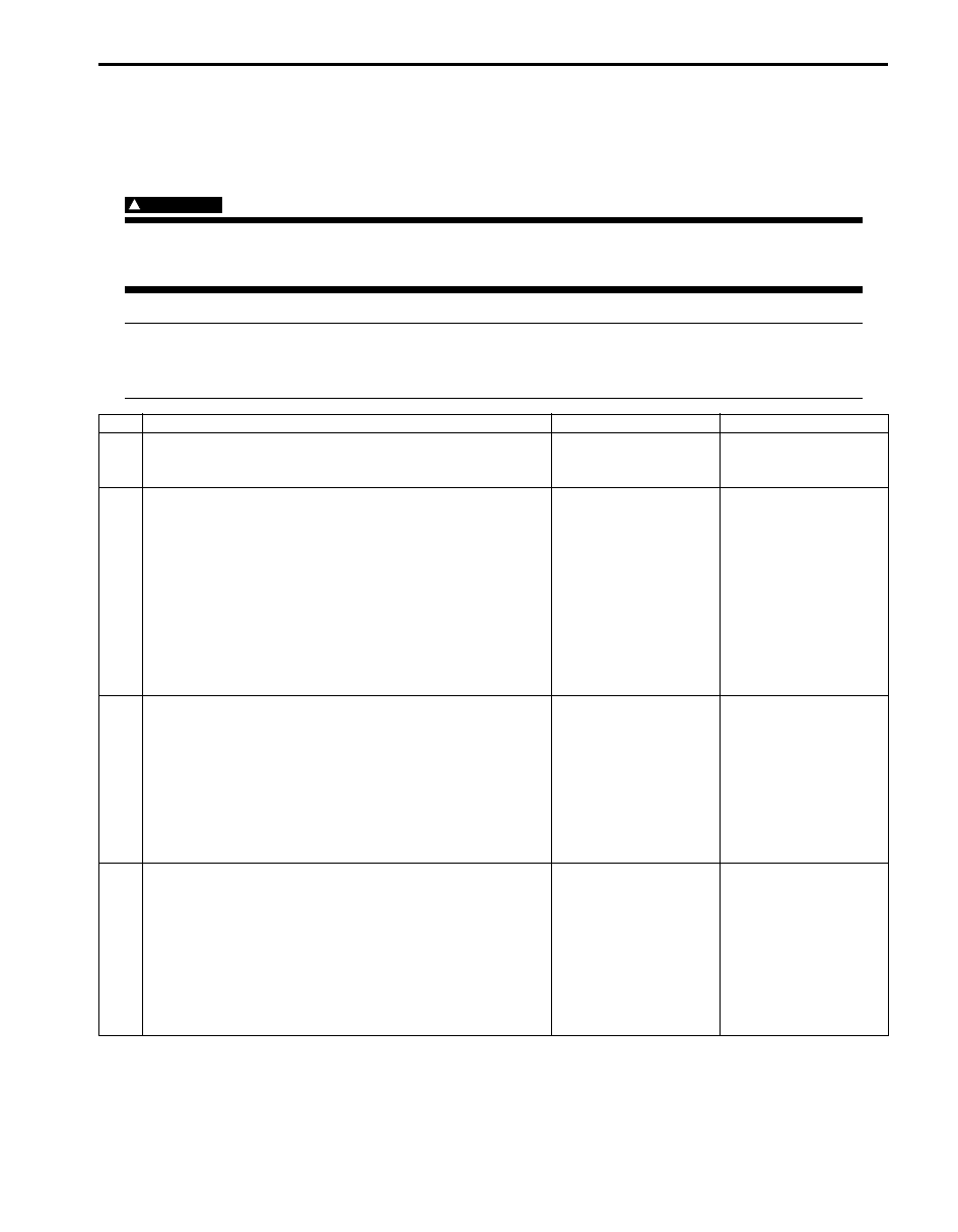
Radiator Cooling Fan High Speed Control System Check
S6JB0B1104092
Wiring Diagram
Refer to “Radiator Cooling Fan Low Speed Control System Check”.
Troubleshooting
WARNING
!
Keep hands, tools, and clothing away from engine cooling fan to help prevent personal injury. This fan
is electric and can come on whether or not the engine is running. The fan can start automatically in
response to the ECT sensor with the ignition switch at the “ON” position.
NOTE
• Before performed troubleshooting, be sure to read the “Precautions of ECM Circuit Inspection”.
• When measuring circuit voltage, resistance and/or pulse signal at ECM connector, connect the
special tool to ECM and/or the ECM connectors referring to “Inspection of ECM and Its Circuits”.
Step
Action
Yes
No
1
Is there DTC(s) of ECT sensor circuit (DTC P0116 / P0117 /
P0118) and/or radiator cooling fan circuit (DTC P0480 /
P0481 / P0482)?
Go to corresponding
DTC flow.
Go to Step 2.
2
Low speed radiator cooling fan control circuit check
1) Connect scan tool to DLC with ignition switch turned
OFF.
2) Start engine and select “DATA LIST” mode on scan tool.
3) Warm up engine until coolant temp. is 92
°C (197.6 °F)
or higher and A/C switch turns OFF (if equipped with A/
C). (If engine coolant temp. dose not rise, check engine
cooling system or ECT sensor.)
Is radiator cooling fan started at low speed when engine
coolant temp. reached above temp.?
Go to Step 3.
Perform from Step 2 to
Step 5 in “Radiator
Cooling Fan Low Speed
Control System Check”.
3
High speed radiator cooling fan control circuit check
1) Start engine and select “DATA LIST” mode on scan tool.
2) Warm up engine until coolant temp. is 102
°C (215.6 °F)
or higher and A/C switch turns OFF (if equipped with A/
C). (If engine coolant temp. dose not rise, check engine
cooling system or ECT sensor.)
Is radiator cooling fan started at high speed when engine
coolant temp. reached above temp?
Radiator cooling fan
control system is in
good condition.
Perform from Step 2 to
Step 5 in DTC P0480
P0481/ P0482: Fan 1 /
Fan 2 / Fan 3 Control
Circuit.
If OK, Go to Step 4.
4
Wire circuit check
1) Disconnect radiator cooling fan relay No.3 from relay
box with ignition switch turned OFF.
2) Turn ON ignition switch.
3) Measure voltage between “BLU/BLK” wire terminal of
radiator cooling fan relay No.3 connector and vehicle
body ground.
Is voltage 10 – 14 V?
Go to Step 5.
“BLU/BLK” wire is open
circuit.
Нет комментариевНе стесняйтесь поделиться с нами вашим ценным мнением.
Текст