Suzuki Grand Vitara JB627. Manual — part 70
1A-229 Engine General Information and Diagnosis:
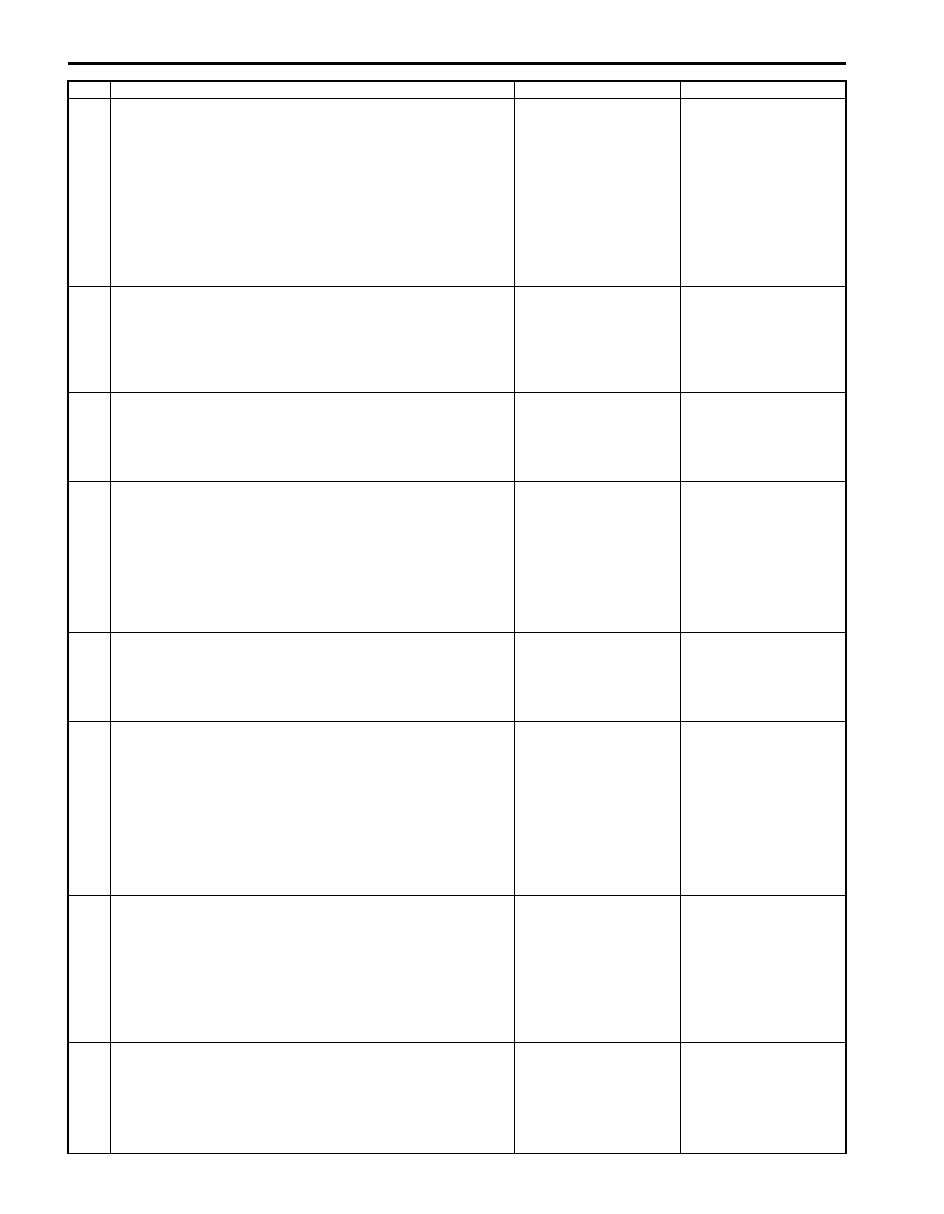
2
Fuel pump relay power supply check
1) Disconnect fuel pump relay from fuse box No.2 with
ignition switch turned OFF.
2) Check for proper connection to fuel pump relay at each
terminal.
3) If OK, turn ON ignition switch, measure voltage between
“WHT/GRN” wire terminal of fuel pump relay connector
and engine ground.
Is voltage 10 – 14 V?
Go to Step 3.
“WHT/GRN” wire is
open or shorted to
ground circuit.
3
Fuel pump relay power supply check
1) Turn ON ignition switch, measure voltage between “BLU/
BLK” wire terminal of fuel pump relay connector and
engine ground.
Is voltage 10 – 14 V?
Go to Step 4.
“BLU/BLK” wire is open
circuit.
4
Fuel pump relay check
1) Check fuel pump relay referring to “Engine and Emission
Control System Relay Inspection in Section 1C”.
Is relay in good condition?
Go to Step 5.
Faulty relay.
5
Fuel pump relay drive signal check
1) Connect fuel pump relay to fuse box No.2.
2) Connect voltmeter between “E23-24” terminal of ECM
connector and vehicle body ground.
3) Measure voltage 2 second after ignition switch is turned
ON.
Is voltage 10 – 14 V?
Go to Step 6.
“WHT/GRN” wire is
open circuit or shorted
to ground circuit.
6
Fuel pump relay drive signal check
1) Measure voltage within 2 second after ignition switch is
turned ON.
Is voltage 0 – 1 V?
Go to Step 7.
Substitute a known
good ECM and recheck.
7
Wire circuit check
1) Turn OFF ignition switch.
2) Detach fuel tank referring to “Fuel Tank Removal and
3) Disconnect connector from fuel pump.
4) Measure resistance between “PNK” wire terminal of fuel
pump connector and vehicle body ground.
Is resistance infinity?
Go to Step 8.
“PNK” wire is shorted to
ground.
8
Fuel pump circuit check
1) Connect service wire between “E23-24” terminal of ECM
connector and vehicle body ground.
2) Turn ON ignition switch, measure voltage between
“PNK” terminal at fuel pump connector and vehicle body
ground.
Is voltage 10 – 14 V?
Go to Step 9.
“PNK” wire is open
circuit.
9
Fuel pump circuit check
1) Turn OFF ignition switch.
2) Measure resistance between “BLK” wire terminal at fuel
pump connector and vehicle body ground.
Is resistance less than 5
Ω
?
Faulty fuel pump.
“BLK” wire is open
circuit.
Step
Action
Yes
No
Engine General Information and Diagnosis: 1A-230
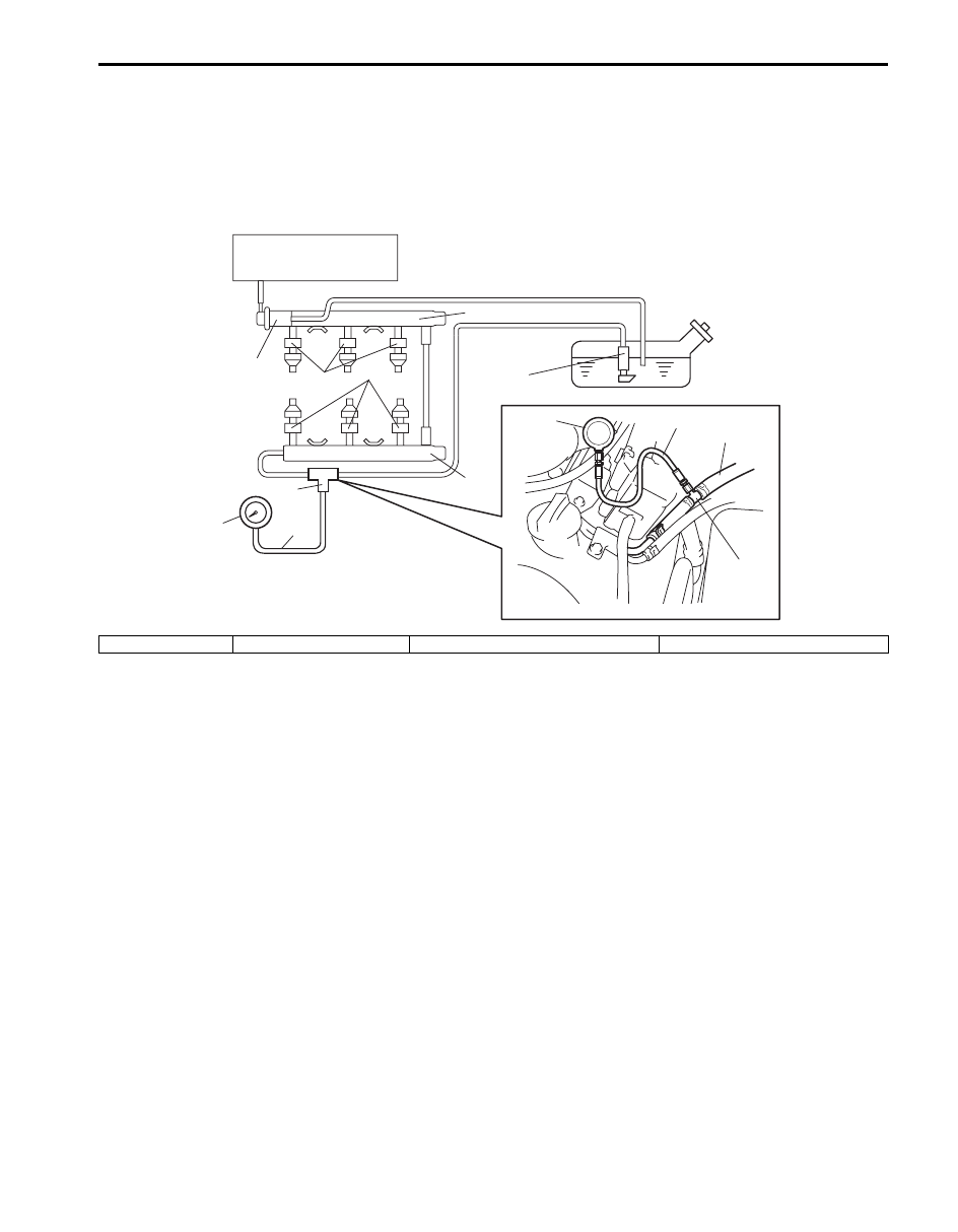
Fuel Pressure Check
S6JB0B1104088
System Diagram
Special tool
(A): 09912–58442
(B): 09912–58432
(C): 09912–58490
(C)
(B)
(A)
(C)
1
(A)
(B)
3
1
1
2
2
4
I6JB01110012-01
1. Injector
2. Delivery pipe
3. Fuel pressure regulator
4. Fuel filter and fuel pump
1A-231 Engine General Information and Diagnosis:
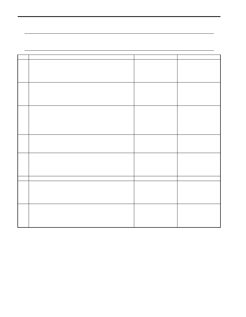
Troubleshooting
NOTE
Before using following flow, check to make sure that battery voltage is higher than 11 V. If battery
voltage is low, pressure becomes lower than specification even if fuel pump and line are in good
condition.
Step
Action
Yes
No
1
Fuel pump operating sound check
1) Remove fuel filler cap and then turn ON ignition switch.
Can you hear operating sound? (Is fuel pump to operate
about 2 seconds after ignition switch is turned ON?)
Go to Step 2.
Go to “Fuel Pump and
Its Circuit Check”.
2
Fuel pressure check
1) Check fuel pressure referring to “Fuel Pressure
Is check result satisfactory?
Go to Step 3.
Go to Step 6.
3
Fuel pressure check
1) Start engine and warm it up to normal operating
temperature.
2) Keep engine speed at 4000 rpm.
Does fuel pressure show about the same value as Step 2?
Go to Step 4.
Go to Step 8.
4
Fuel line check
1) Check fuel pipe, fuel hose and joint for fuel leakage.
Are they in good condition?
Go to Step 5.
Repair or replace
defective part.
5
Fuel line check
1) Check fuel pipe, fuel hose and joint for damage or
deform.
Are they in good condition?
Faulty fuel pressure
regulator.
Repair or replace
damaged or damaged
part.
6
Was fuel pressure higher than specification in Step 2?
Go to Step 7.
Go to Step 8.
7
Fuel line check
1) Check fuel pipe, fuel hose and joint for damage or
deform.
Are they in good condition?
Faulty fuel pressure
regulator.
Repair or replace
damaged or damaged
part.
8
Fuel line check
1) Check fuel pipe, fuel hose and joint for damage or
deform.
Are they in good condition?
Clogged fuel filter, faulty
fuel pump, faulty fuel
pressure regulator or
fuel leakage from hose
connection in fuel tank.
Repair or replace
defective part.
Engine General Information and Diagnosis: 1A-232
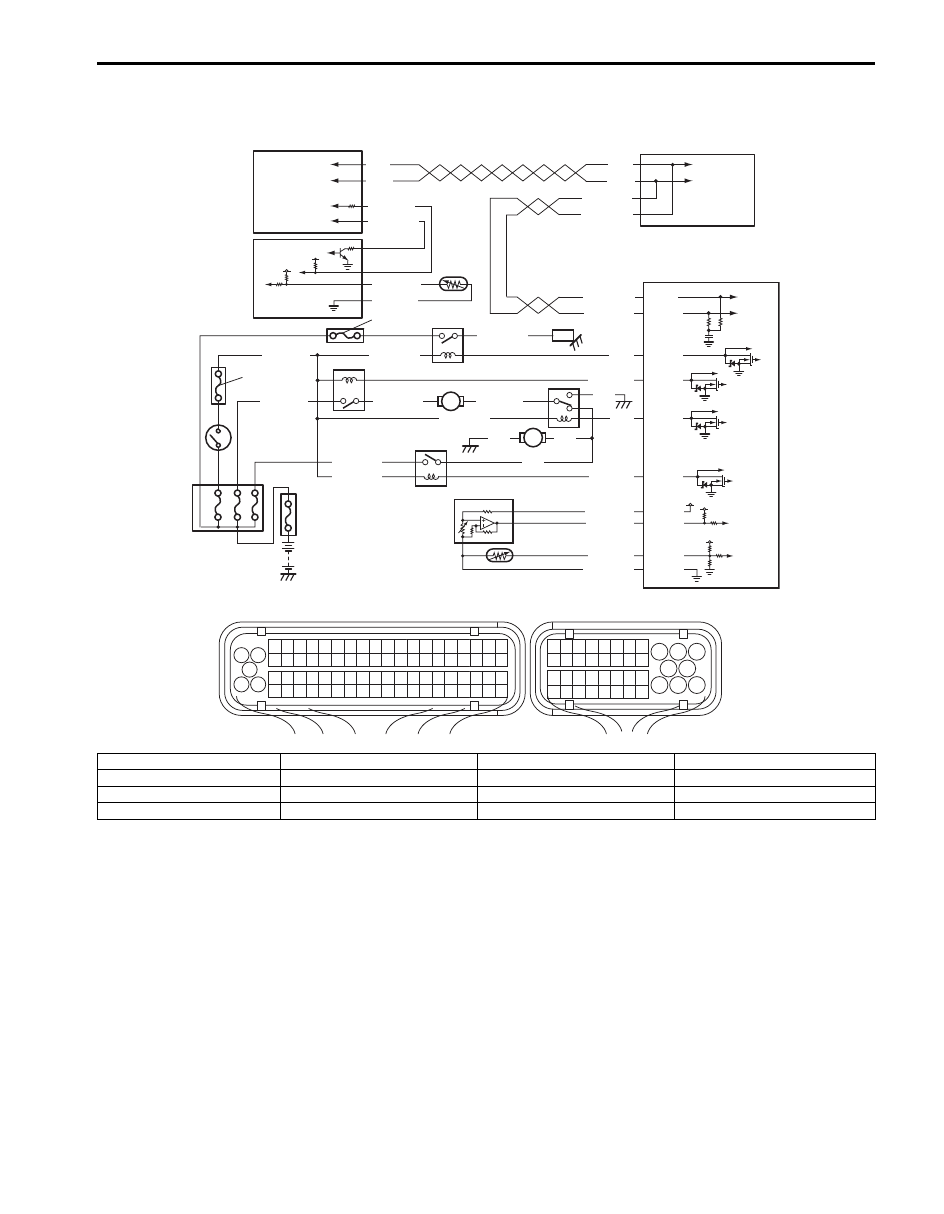
A/C System Circuits Check
S6JB0B1104089
Wiring Diagram
1
3 2
4
5
6
7
8
9
1110
12
13
14
15
16
17
18
19
20
17
18
19
20
21
22
23
24
25
26
27
28
29
30
31
33
34
35
36
37
38
39
40
32
1
2
3
4
5
6
7
8
9
10
11
12
13
14
15
16
21
22
23
24
25
26
27
28
29
30
31
32
33
34
35
36
37
38
39
40
41
42
43
44
45
46
47
48
49
50
51
52
53
54
55
56
57
58
59
60
61
62
63
64
65
66
67
68
69
70
71
72
73
74
75
76
77
78
79
80
81
E23
C37
5V
RED/BLK
BLU/BLK
BLK
RED
YEL/GRN
RED/YEL
BLK
BLU
BLU
BLU/WHT
YEL/GRN
5V
WHT/BLU
WHT/RED
RED
WHT
WHT/BLU
WHT/RED
RED
WHT
5V
PNK/GRN
YEL/RED
WHT/BLK
BLK/RED
12V
PNK
GRY/RED
GRY/BLK
WHT/RED
E23-37
E23-15
E23-23
E23-14
C37-49
C37-48
C37-26
C37-67
E23-17
E23-9
YEL/GRN
YEL/GRN
5V
PPL/YEL
GRY/GRN
BLU/RED
BLU/YEL
1
3
5
7
8
10
6
9
11
13
14
12
15
16
4
2
I6JB01110013-03
1. BCM
5. Evaporator temperature sensor
9. Compressor
13. Radiator cooling fan No.1
2. ABS or ESP
® control module
6. “IG2 SIG” fuse
10. Radiator cooling fan relay No.1
14. Radiator cooling fan No.2
3. HVAC control module
7. “CPRSR” fuse
11. Radiator cooling fan relay No.2
15. A/C refrigerant pressure sensor
4. ECM
8. Compressor relay
12. Radiator cooling fan relay No.3
16. ECT sensor
Нет комментариевНе стесняйтесь поделиться с нами вашим ценным мнением.
Текст