Suzuki Grand Vitara JB627. Manual — part 71
1A-233 Engine General Information and Diagnosis:
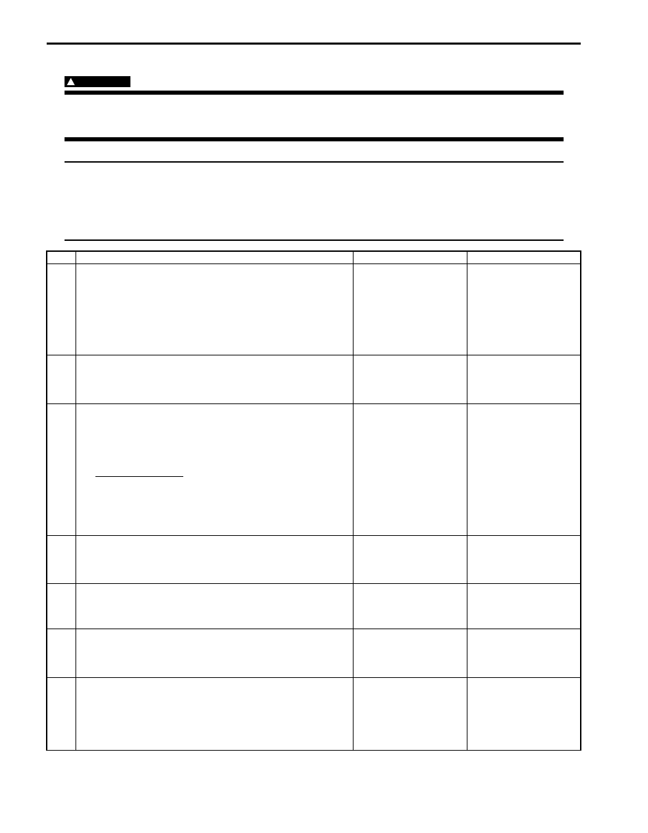
Troubleshooting
WARNING
!
Keep hands, tools, and clothing away from A/C condenser fan to help prevent personal injury. This fan
is electric and can come on whether or not the engine is running. The fan can start automatically in
response to the ECT sensor with the ignition switch in the “ON” position.
NOTE
• Before performed troubleshooting, be sure to read the “Precautions of ECM Circuit Inspection”.
• When measuring circuit voltage, resistance and/or pulse signal at ECM connector, connect the
special tool to ECM and/or the ECM connectors referring to “Inspection of ECM and Its Circuits”.
• When A/C evaporator outlet air temp. is below 0
°C (32 °F), A/C remains OFF. This condition is not
abnormal.
Step
Action
Yes
No
1
Check DTC in ECM (Reception data check from BCM)
1) Connect scan tool to DLC with ignition switch turned
OFF.
2) Turn ON ignition switch.
3) Check DTC for reception data from BCM.
Is there DTC U0140?
Go to applicable DTC
diag. flow.
Go to Step 2.
2
DTC check of HVAC control module
1) Check HVAC control module for DTC.
Is there DTC(s)?
Go to applicable DTC
diag. flow.
Go to Step 3.
3
A/C switch signal circuit check
1) Start engine and select “DATA LIST” mode on scan tool.
2) Check A/C switch signal under following conditions
respectively.
A/C switch signal
Engine running, A/C switch OFF: OFF
Engine running, A/C switch ON and blower speed
selector turned 1st position or more: ON
Is check result satisfactory?
Go to Step 4.
Check HVAC control
module and its circuit.
4
DTC check of ECT sensor circuit
1) Check ECM for DTC of ECT sensor circuit.
Is there DTC P0116, DTC P0117 or DTC P0118?
Go to applicable DTC
diag. flow.
Go to Step 5.
5
Radiator cooling fan control system check
Is radiator cooling fan started when A/C and blower speed
selector switch are turned ON with engine running?
Go to Step 11.
Go to Step 6.
6
Radiator cooling fan control circuit check
1) Check DTC with scan tool.
Are DTC P0480, DTC P0481 and/or DTC P0482 detected?
Go to applicable DTC
diag. flow.
Go to Step 7.
7
Evaporator temperature sensor check
1) Check evaporator temperature sensor referring to “A/C
Evaporator Temperature Sensor Inspection in Section
7B”.
Is resistance within specification?
Go to Step 8.
Faulty evaporator
temperature sensor.

Engine General Information and Diagnosis: 1A-234
8
DTC check of A/C refrigerant pressure sensor circuit
1) Connect scan tool to DLC with ignition switch turned
OFF.
2) Turn ON ignition switch.
3) Check ECM for DTC of A/C refrigerant pressure sensor
circuit.
Is there DTC P0532 or DTC P0533?
Go to applicable DTC
diag. flow.
Go to Step 9.
9
A/C refrigerant pressure sensor voltage check
1) Check A/C refrigerant pressure sensor voltage referring
to “Inspection of ECM and Its Circuits”.
Is voltage within specified value?
Go to Step 10.
Check amount of
refrigerant. If OK,
replace A/C refrigerant
pressure sensor.
10 Radiator cooling fan check
1) Check radiator cooling fan referring to “Radiator Cooling
Fan Motor On-Vehicle Inspection in Section 1F”.
Is check result satisfactory?
Radiator cooling fan
drive circuit malfunction.
Replace radiator cooling
fan motor.
11 A/C compressor control system check
Is A/C compressor started when A/C and blower speed
selector switch are turned ON with engine running?
A/C system is in good
condition.
Go to Step 12.
12 A/C compressor relay circuit check
1) Measure voltage between “E23-37” wire terminal of
ECM connector and vehicle body ground under following
conditions respectively.
Voltage between “E23-37” terminal of ECM
connector and ground
While engine running and A/C switch turned OFF: 10
– 14 V
While engine running, A/C and blower speed
selector switch turned ON: 0 – 1 V
Is check result satisfactory?
Go to Step 13.
Go to Step 14.
13 A/C compressor relay check
1) Check A/C compressor relay referring to “A/C
Compressor Relay Inspection in Section 7B”.
Is it in good condition?
A/C compressor drive
circuit malfunction.
Replace A/C
compressor relay.
14 A/C compressor relay circuit check
1) Remove A/C compressor relay with ignition switch
turned OFF.
2) Turn ON ignition switch, measure voltage between “YEL/
GRN” wire terminal of A/C compressor relay connector
and vehicle body ground.
Is voltage 10 –14 V?
Go to Step 15.
“YEL/GRN” wire is open
circuit.
15 A/C compressor relay check
1) Check A/C compressor relay referring to “A/C
Compressor Relay Inspection in Section 7B”.
Is it in good condition?
“PNK” wire is open
circuit. If OK, substitute
a known good ECM and
recheck.
Replace A/C
compressor relay.
Step
Action
Yes
No
1A-235 Engine General Information and Diagnosis:
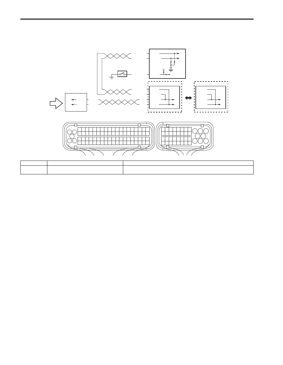
Electric Load Signal Circuit Check
S6JB0B1104090
Wiring Diagram
WHT/BLU
BLU/ORN
WHT/RED
E23-9
E23-17
1
RED
WHT
E03-12
E03-6
WHT/BLU
WHT/RED
E03-8
E03-10
RED
WHT
G31-3
G31-1
2
C37-8
C37
E23
3
6
12V
5
1
3 2
4
5
6
7
8
9
1110
12
13
14
15
16
17
18
19
20
17
18
19
20
21
22
23
24
25
26
27
28
29
30
31
33
34
35
36
37
38
39
40
32
1
2
3
4
5
6
7
8
9
10
11
12
13
14
15
16
21
22
23
24
25
26
27
28
29
30
31
32
33
34
35
36
37
38
39
40
41
42
43
44
45
46
47
48
49
50
51
52
53
54
55
56
57
58
59
60
61
62
63
64
65
66
67
68
69
70
71
72
73
74
75
76
77
78
79
80
81
E53-13
E53-44
E53-46
E53-42
4
I6JB01110014-03
1. ECM
3. ABS control module
5. PSP switch
2. BCM
4. ESP
® control module
6. Electric load signal (blower motor signal, rear defogger signal, headlight signal and A/
C switch signal, etc.)
Engine General Information and Diagnosis: 1A-236
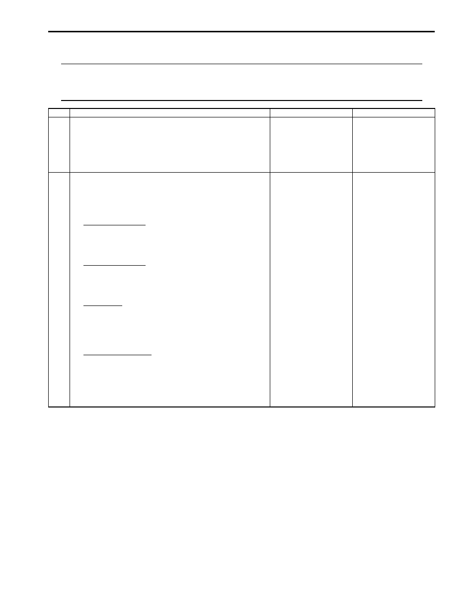
Troubleshooting
NOTE
• Before performed troubleshooting, be sure to read the “Precautions of ECM Circuit Inspection”.
• When measuring circuit voltage, resistance and/or pulse signal at ECM connector, connect the
special tool to ECM and/or the ECM connectors referring to “Inspection of ECM and Its Circuits”.
Step
Action
Yes
No
1
DTC check
1) Connect scan tool to DLC with ignition switch turned
OFF.
2) Turn ON ignition switch and check DTC.
Is there DTC U0073 and/or U0140?
Go to applicable DTC
diag. flow.
Go to Step 2.
2
Electric load signal circuit check
1) Start engine and select “DATA LIST” mode on scan tool.
2) Check electric load signal under following conditions
respectively.
A/C switch signal
Engine running, A/C switch OFF: OFF
Engine running, A/C switch ON and blower speed
selector turned 1st position or more: ON
Blower fan signal
Engine running, blower speed selector OFF: OFF
Engine running, blower speed selector 5th position
or more: ON
PSP signal
Engine running, steering wheel to neutral position:
OFF
Engine running, turning steering wheel to the right
or left as far as it stops: ON
Electric load signal
Engine running, rear defogger switch or headlight
switch OFF: OFF
Engine running, rear defogger switch or headlight
switch ON: ON
Is check result satisfactory?
Electric load signal
circuit is in good
condition
Check defective signal
circuit.
Нет комментариевНе стесняйтесь поделиться с нами вашим ценным мнением.
Текст