Suzuki Grand Vitara JB627. Manual — part 69
1A-225 Engine General Information and Diagnosis:
6
ECM ground circuit check
1) Turn ignition switch to OFF position.
2) Disconnect connectors from ECM.
3) Measure resistance between each “C37-39”, “C37-58”,
“C37-59”, “C37-73”, “C-37-80” and “C37-81” terminals of
ECM connector and body ground.
Is resistance 1
Ω
or less?
Substitute a known
good ECM and recheck.
“BLK/ORN” or “BLK/
YEL” wire is open or
high resistance circuit.
7
Main relay circuit check
1) Disconnect connectors from ECM with ignition switch
turned OFF.
2) Using service wire, ground “E23-16” terminal of ECM
connector and measure voltage between each “E23-2”
and “E23-3” terminals of ECM connector and body
ground.
Is voltage 10 – 14 V?
Go to Step 11.
Go to Step 8.
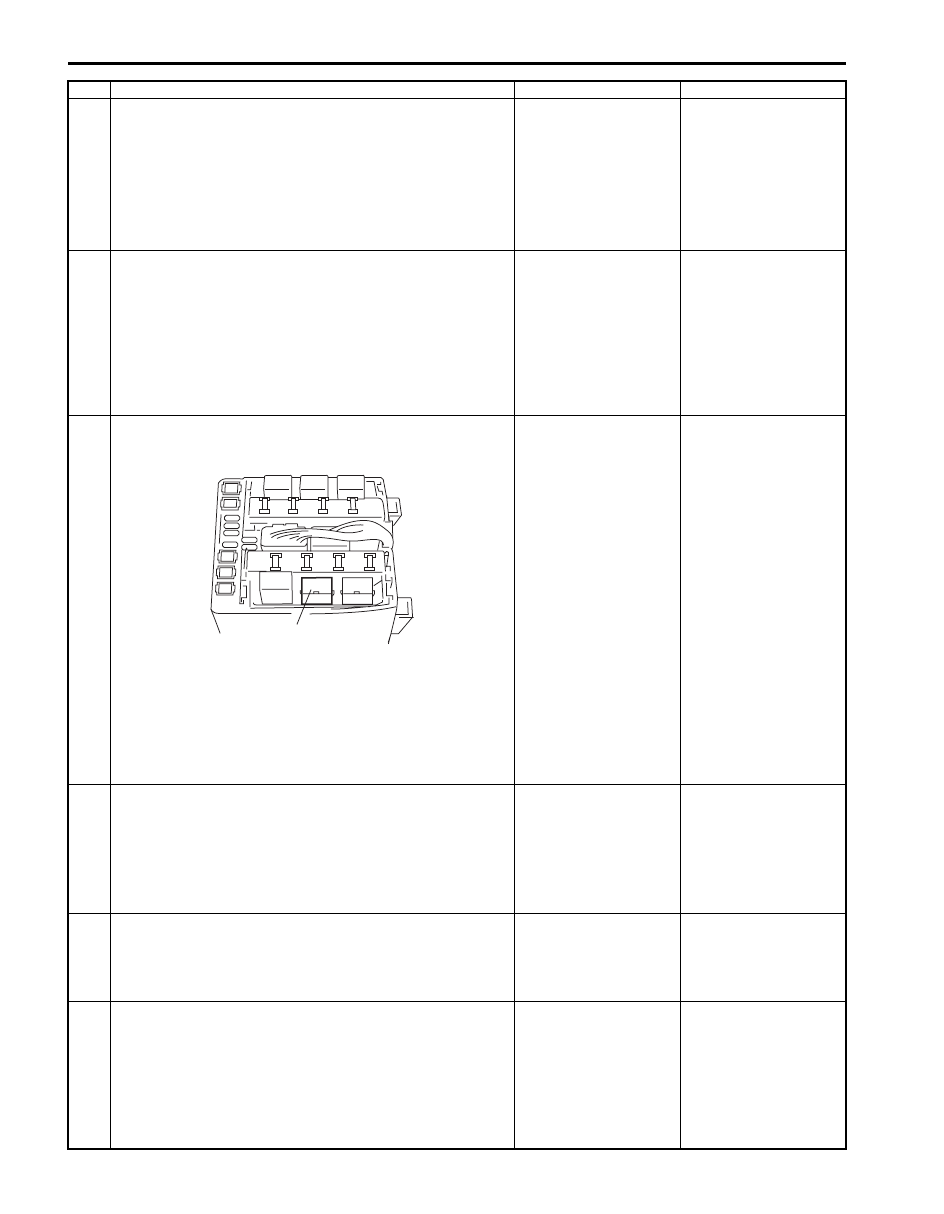
8
Main relay circuit check
1) Remove main relay (1) from fuse box No.2.
2) Check for proper connection to main relay connector at
“BLU/BLK” and “BLK/RED” wire terminals.
3) If OK, measure resistance between each “E23-2” and
“E23-3” wire terminals of ECM connector and “BLU/BLK”
wire terminal of main relay connector.
Is resistance 1
Ω
or less?
Go to Step 9.
“BLU/BLK” wire is open
circuit or high resistance
circuit.
9
Main relay circuit check
1) Remove main relay from fuse box No.2 with ignition
switch turned OFF.
2) Measure voltage between “BLK/RED” wire terminal of
main relay connector and body ground.
Is voltage 10 – 14 V?
Go to Step 10.
“BLK/RED” wire is open
circuit.
10 Main relay check
1) Check main relay referring to “Engine and Emission
Control System Relay Inspection in Section 1C”.
Is main relay in good condition?
“BLU” wire is open or
high resistance circuit.
Replace main relay.
11 Sensor 5 V power source circuit check
1) Connect connectors to ECM with ignition switch turned
OFF.
2) Turn ON ignition switch, measure each voltage between
“C37-45” and “C37-49” terminal of ECM connector and
vehicle body ground.
Is each voltage 4 – 6 V?
ECM power and ground
circuit is in good
condition.
Go to Step 12.
Step
Action
Yes
No
1
I5JB0C110017-01
Engine General Information and Diagnosis: 1A-226
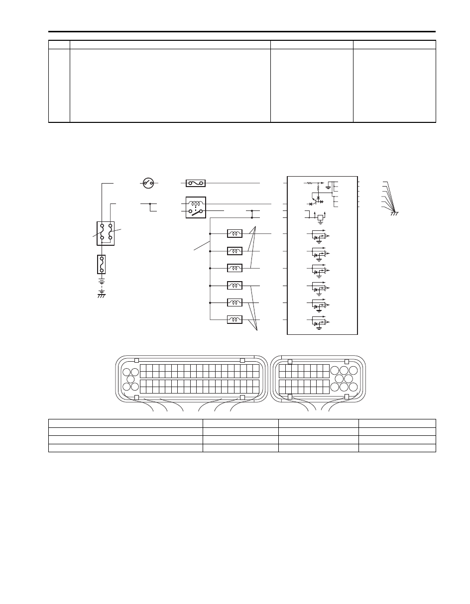
Fuel Injector Circuit Check
S6JB0B1104086
Wiring Diagram
12 Sensor 5 V power source circuit check
1) Disconnect connectors from ECM, TP sensor, MAP
sensor (if equipped), A/C refrigerant pressure sensor (if
equipped) with ignition switch turned OFF.
2) Measure each resistance between “C37-45” and “C37-
49” terminal of ECM connector and vehicle body ground.
Is each resistance infinity?
Check internal short
circuit of TP sensor,
MAP sensor (if
equipped) and/or A/C
refrigerant pressure
sensor (if equipped).
“GRY/RED” and/or
“BLK” wire is shorted to
ground circuit.
Step
Action
Yes
No
BLU/BLK
BLU/BLK
BLU/BLK
BLK/RED
BLK/RED
BLK/RED
BLU
12V 5V
E23-8
E23-16
E23-2
E23-3
WHT/GRN
C37-59
C37-58
C37-39
C37-73
C37-80
BLK/YEL
BLK/ORN
BLK/ORN
BLK/YEL
BLK/YEL
1
3 2
4
5
6
7
8
9
1110
12
13
14
15
16
17
18
19
20
17
18
19
20
21
22
23
24
25
26
27
28
29
30
31
33
34
35
36
37
38
39
40
32
1
2
3
4
5
6
7
8
9
10
11
12
13
14
15
16
21
22
23
24
25
26
27
28
29
30
31
32
33
34
35
36
37
38
39
40
41
42
43
44
45
46
47
48
49
50
51
52
53
54
55
56
57
58
59
60
61
62
63
64
65
66
67
68
69
70
71
72
73
74
75
76
77
78
79
80
81
E23
C37
BLK/ORN
C37-81
BLK/YEL
BLK/WHT
C37-15
C37-34
C37-14
C37-33
C37-13
C37-32
PNK/BLK
PNK/GRN
PNK/BLU
GRY/GRN
GRY/BLK
PNK
11
10
2
3
4
5
6
7
8
9
1
13
12
P
C
C
I6JB01110010-02
P: Fuel injector power supply circuit
3. ECM
7. No.4 injector
11. Ignition switch
C: Fuel injector control circuit
4. No.1 injector
8. No.5 injector
12. “FI” fuse
1. Fuse box No.2
5. No.2 injector
9. No.6 injector
13. “IGN” fuse
2. Main relay
6. No.3 injector
10. “IG COIL” fuse

1A-227 Engine General Information and Diagnosis:
Troubleshooting
NOTE
• Before performed troubleshooting, be sure to read the “Precautions of ECM Circuit Inspection”.
• When measuring circuit voltage, resistance and/or pulse signal at ECM connector, connect the
special tool to ECM and/or the ECM connectors referring to “Inspection of ECM and Its Circuits”.
Step
Action
Yes
No
1
Fuel injector check for operating sound
1) Using sound scope, check each injector for operating
sound at engine cranking.
Do all 6 injector make operating sound?
Fuel injectors circuit is
in good condition.
Go to Step 2.
2
Fuel injector resistance check
1) Disconnect connectors from fuel injectors with ignition
switch turned OFF.
2) Check for proper terminal connection to all fuel injectors
and ECM connector.
3) If connections are OK, check all fuel injectors for
resistance referring to “Fuel Injector On-Vehicle
Inspection in Section 1G”.
Are all injectors in good condition?
Go to Step 3.
Faulty fuel injector.
3
Fuel injector insulation resistance check
1) Check that there is insulation between each fuel injector
terminal and engine ground.
Is there insulation?
Go to Step 4.
Faulty fuel injector.
4
Fuel injector power supply check
1) Measure voltage between each fuel injector connector
power supply circuit and engine ground with ignition
switch turned ON.
Is each voltage 10 – 14 V?
Go to Step 5.
Fuel injector power
supply circuit is open or
shorted to ground
circuit.
If it is in good condition,
go to “ECM Power and
Ground Circuit Check”.
5
Wire harness check
1) Disconnect connector from ECM with ignition switch
turned OFF.
2) Check that each fuel injector circuit is as follows.
• Wiring harness resistance of each fuel injector control
circuit is less than 3
Ω
• Insulation resistance of each fuel injector control
circuit is infinity between each fuel injector connector
and vehicle body ground
• Circuit voltage of each fuel injector control circuit is 0
– 1 V with ignition switch turned ON
Are they in good condition?
Check fuel injector for
performance referring to
“Fuel Injector Inspection
in Section 1G”. If OK,
substitute a known good
ECM and recheck.
Fuel injector control
circuit is open, short or
high resistance.
Engine General Information and Diagnosis: 1A-228
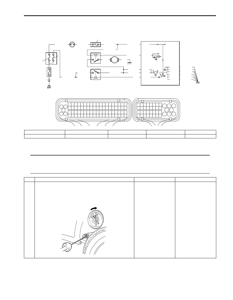
Fuel Pump and Its Circuit Check
S6JB0B1104087
Wiring Diagram
Troubleshooting
NOTE
• Before performed troubleshooting, be sure to read the “Precautions of ECM Circuit Inspection”.
• When measuring circuit voltage, resistance and/or pulse signal at ECM connector, connect the
special tool to ECM and/or the ECM connectors referring to “Inspection of ECM and Its Circuits”.
BLU/BLK
WHT/GRN
BLU/BLK
BLU/BLK
BLK/RED
BLK/RED
BLK/RED
BLU
12V 5V
E23-8
E23-24
E23-16
E23-2
E23-3
WHT/GRN
C37-59
C37-58
C37-39
C37-73
C37-80
BLK/YEL
BLK/ORN
BLK/ORN
BLK/YEL
BLK/YEL
1
3 2
4
5
6
7
8
9
1110
12
13
14
15
16
17
18
19
20
17
18
19
20
21
22
23
24
25
26
27
28
29
30
31
33
34
35
36
37
38
39
40
32
1
2
3
4
5
6
7
8
9
10
11
12
13
14
15
16
21
22
23
24
25
26
27
28
29
30
31
32
33
34
35
36
37
38
39
40
41
42
43
44
45
46
47
48
49
50
51
52
53
54
55
56
57
58
59
60
61
62
63
64
65
66
67
68
69
70
71
72
73
74
75
76
77
78
79
80
81
E23
C37
BLK/ORN
C37-81
BLK/YEL
BLK/WHT
BLK/WHT
BLK/WHT
BLK
PNK
1
7
6
3
4
5
2
9
8
I6JB01110011-03
1. Fuse box No.2
3. ECM
5. Fuel pump
7. Ignition switch
9. “IGN” fuse
2. Main relay
4. Fuel pump relay
6. “IG COIL” fuse
8. “FI” fuse
Step
Action
Yes
No
1
Fuel pump control system check for operation
Is fuel pump heard to operate 2 sec. after ignition switch is
turned ON?
Fuel pump circuit is in
good condition.
Go to Step 2.
I2RH01110132-01
Нет комментариевНе стесняйтесь поделиться с нами вашим ценным мнением.
Текст