Suzuki: Engine K6A-YH6. Manual — part 8
THEORY OF OPERATION
4-9
4
4.5 Cylinder Head and Valve Train
Figure 4-10
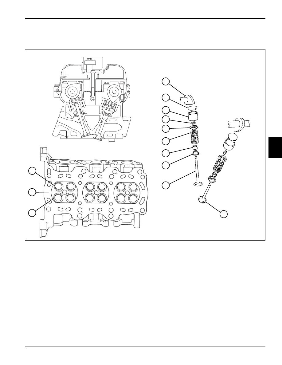
The twin cam, 4-valve per cylinder head is constructed
with an aluminum alloy that is both lightweight and
efficient in heat dissipation. Valve angle is set narrow to
also make for a compact head design.
The spark plug port (12) is located in the center of the
combustion chamber, with the combustion chamber
being a pent-roof design for improved combustion
efficiency.
The intake (11) and exhaust ports (13) are arranged in a
cross-flow style with each cylinder having two intake and
two exhaust valves for improved intake and exhaust
efficiency. Intake valves are faced with a dual angle while
exhaust valves have a single angle face.
The valve spring retainer (5), valve spring (6), valve seal
(7), and valve spring seat (8) are all installed over the
valve stem and held in place with the retainer locks (4).
The valves (9 and 10) are pushed down directly with the
camshaft lobe (1) via shim (2) and tappet (3). Valve lash
is adjusted by varying the thickness of the shim (2).
1
Camshaft Lobe
6
Valve Spring
11
Intake Port
2
Shim
7
Valve Seal
12
Spark Plug Port
3
Tappet
8
Valve Spring Seat
13
Exhaust Port
4
Retainer Lock
9
Intake Valve
5
Valve Spring Retainer
10
Exhaust Valve
TN0750, 0523, 0493
1
2
3
6
7
8
9
4
13
12
11
10
5
4-10
THEORY OF OPERATION
4
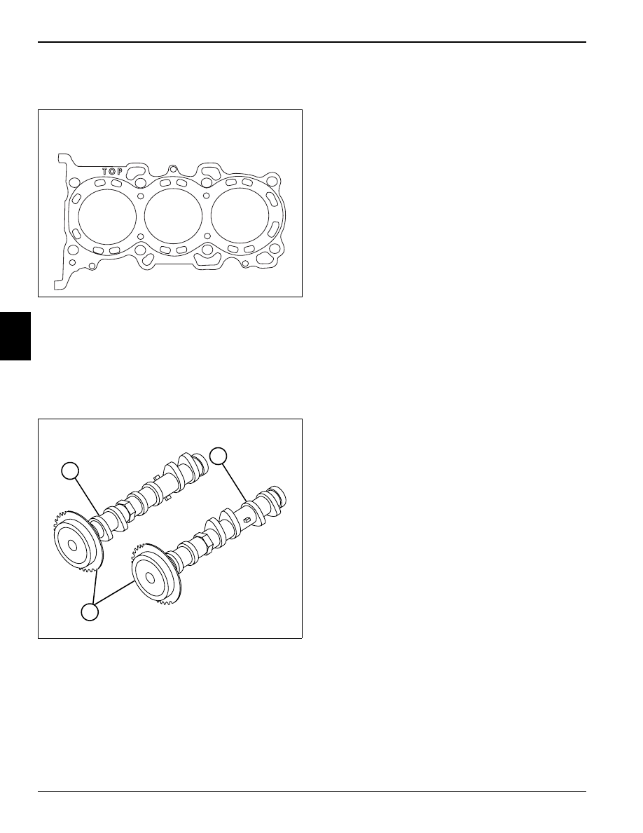
Head Gasket
Figure 4-11
The cylinder head gasket is made of a 2-layer laminated
stainless steel. The surface of the cylinder head gasket is
treated with a rubberized coating.
Camshaft
Figure 4-12
The intake (1) and exhaust (2) camshafts are made of
lightweight hollow cast iron. The camshaft timing
sprockets (3) are press fit onto the front of the camshafts
and are serviceable only with the camshaft. Engine oil
flows through the hollow center of the cams, direct
lubricating the camshaft journals. Camshaft lobes,
tappets, and valves are indirect splash lubricated from
the camshaft journals.
TN0494
TN0505
1
2
3
THEORY OF OPERATION
4-11
4
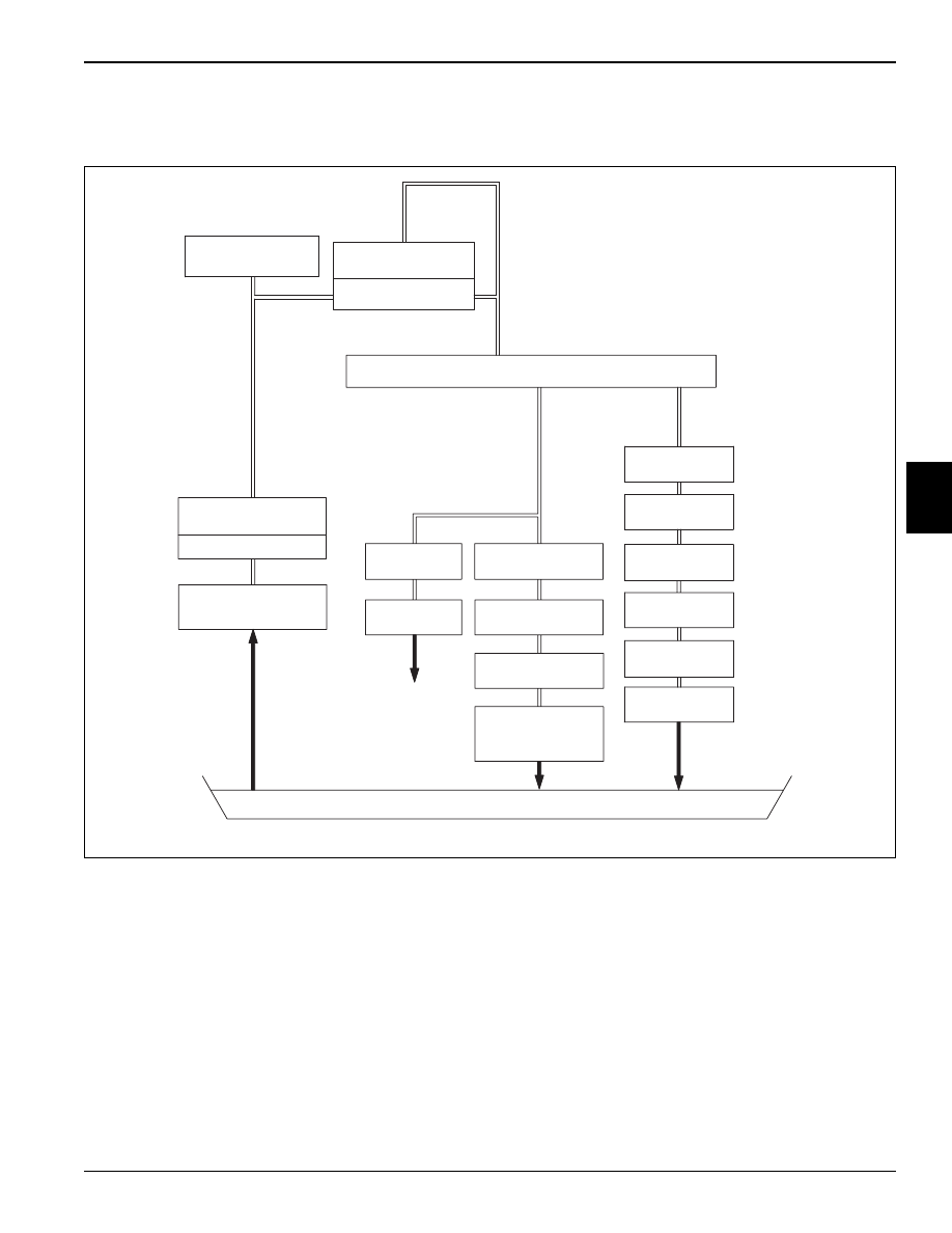
4.6 Lubrication System
Figure 4-13
The K6A engine uses a wet sump lubrication system,
which force feeds oil through the full-flow oil filter and the
entire lubrication system.
The inner rotor of the oil pump is driven by the
crankshaft. The outer rotor is driven with the inner rotor.
The pump creates suction, and draws oil through the oil
pickup strainer from the oil pan. The oil is pumped
through the main passage of the front cover into the
engine block and the oil filter.
An oil pressure switch is located in this passage to
monitor and warn of low oil pressure.
The oil is routed through a full-flow oil filter equipped with
a bypass valve. The bypass valve will open and allow oil
flow to the engine in the event the filter becomes plugged
or damaged and will not allow oil flow to the engine. From
the filter, the oil flows into the main gallery. The main
gallery sends oil to both the cylinder block and the
cylinder head.
OIL PRESSURE
SWITCH
BYPASS VALVE
LUBE OIL FILTER
CYLINDER BLOCK MAIN GALLERY
.
REGULATOR
VALVE
LUBE OIL PUMP
OIL SUCTION PIPE
(STRAINER)
TENSION
ADJUSTER
TIMING
CHAIN
FRONT CAM
JOURNAL
CAMSHAFT
CAM JOURNALS
CAM FACE
TAPPETS,
PISTON PIN
CONNECTING
ROD
ROD
JOURNALS
ROD PIN
CRANK PIN
CRANK
JOURNALS
OIL PAN
VALVES
TN0751
4-12
THEORY OF OPERATION
4
From the main gallery, oil distributes to the crankshaft
journals and crank pins. The crankshaft is drilled
between the crank pins and rod pins. Oil flows through to
the rod pins, lubricating the rod journals, and then passes
into a drilled passage in the connecting rod. Oil also
seeps out the sides of the crank and rod journals to
lubricate the sides of the journals. Any excess oil from
lubricating the crank and rod journals passes out from
the journals and returns to the oil pan.
The passage in the connecting rod leads to an oil jet at
the top of the large end of the rod.This jet sprays oil
upward to lubricate the cylinder walls, piston, and piston
pin. Excess oil drains back to the oil pan.
Oil from the main gallery is also sent up to the cylinder
head. On its way up to the cylinder head, the oil passes
through a restrictor orifice. This limits the amount of oil to
the head and ensures the proper amount of oil in the
lower end of the engine.
When the oil reaches the cylinder head, the passage
splits. Oil is sent to the timing chain tension adjuster to
maintain proper chain tension. An orifice in the tension
adjuster also provides a spray to lubricate the timing
chain.
The oil is also sent up to the front of the cylinder head,
where it lubricates both of the front camshaft journals. Oil
enters both camshafts from the front journals and flows
through the camshafts, where it exits lube holes for each
of the other camshaft journals. Excess oil exits the
journals and splash lubricates the camshaft faces and
tappets. Oil seeps through oil holes in the tappet
adjusting shims and tappets to lubricate the valves.
Excess oil then flows through return passages from the
cylinder head and returns to the oil pan.
Нет комментариевНе стесняйтесь поделиться с нами вашим ценным мнением.
Текст