Suzuki: Engine K6A-YH6. Manual — part 20

7-34
REPAIR
7
Outer Rotor Side Clearance
Figure 7-81
1.
Place a straightedge (1) across the oil pump rotor
bore. Use a feeler gauge (2) to measure the
clearance between the straightedge and the outer
rotor side surface. If measurement is beyond service
limit, replace the oil pump assembly.
Oil Pump Outer Rotor Side Clearance Limit:
0.003—0.005 in. (0.076—0.127 mm)
Inner Rotor and Pump Case Clearance
Figure 7-82
1.
Using a micrometer, measure the outside diameter of
the inner rotor shoulder (1).
2.
Measure the inside diameter of the oil pump bore
hole (2). If measurements are not within service limit,
replace oil pump assembly.
Inner Rotor and Pump Case Clearance:
0.001—0.003 in. (0.025—0.076 mm)
TN0392
1
2
TN0394
1
2

REPAIR
7-35
7
Relief Valve Spring
Figure 7-83
1.
Use a veneer caliper to measure the free length of
relief valve spring (1). If relief valve spring measures
less than specification, replace the spring.
Oil Pump Relief Valve Spring Free Length: 2.063 in.
(52.40 mm)
2.
Using a spring compression gauge (2), compress
relief valve spring to specification and record the
force reading. If force reading is less than
specification, replace the spring.
Oil Pump Relief Valve Spring Tension at 1.516 in.
(38.5 mm) of Length: 17.3 lb-ft (23.45 N•m)
Required Tools
Veneer Caliper
Spring Compression Gauge
TN0558, 0559
1
2

7-36
REPAIR
7
Installation
Figure 7-84
1.
Using bushing, bearing, and seal driver (1), install
new oil seal (2) into front cover (3).
Figure 7-85
NOTE
Install inner and outer rotor as previously marked.
2.
Install relief valve (11), spring (10), retainer (9), and
circlip (8).
3.
Install inner rotor (4) and outer rotor (5).
4.
Install oil pump housing (6) using screws (7). Tighten
to specification.
Oil Pump Housing Torque: 60 lb-in. (6.78 N•m)
Required Tools
Bushing, Bearing and Seal Driver (Suzuki PN
09913-75520) or equivalent
TN0561
1
2
3
TN0557
4
5
6
7
8
11
10
9
REPAIR
7-37
7
7.8 Cylinder Block and Lower
Crankcase
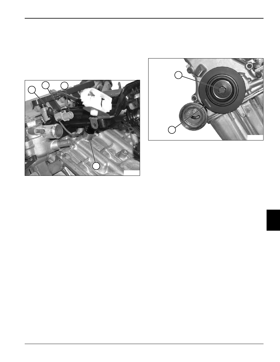
Knock Sensor
Removal and Installation
Figure 7-86
1.
Use a small screwdriver to depress internal tab (2)
and release electrical connector (3) from bracket (1).
2.
Remove knock sensor (4) from cylinder block.
3.
Inspect and replace as needed.
Installation Notes
Install knock sensor by reversing the order of removal.
Tighten knock sensor to specification.
Knock Sensor Torque: 203 lb-in. (23 N•m)
Crankshaft Pulley
Removal and Installation
Figure 7-87
1.
Remove cap screw (1) and crankshaft pulley (2).
2.
Inspect and replace as needed.
Installation Notes
Install crankshaft pulley by reversing the order of
removal.
Tighten crankshaft pulley cap screw to specification.
Crankshaft Pulley Cap Screw: 72 lb-ft (98 N•m)
TN0718
1
2
3
4
TN0721
2
1
Нет комментариевНе стесняйтесь поделиться с нами вашим ценным мнением.
Текст