Suzuki: Engine K6A-YH6. Manual — part 18
7-26
REPAIR
7
Installation
See Figures 7-65 through 7-67.
IMPORTANT
Make sure cylinder head and cylinder block are free
of oil and debris.
Make sure cylinder head bolt holes are free of oil,
water, or debris.
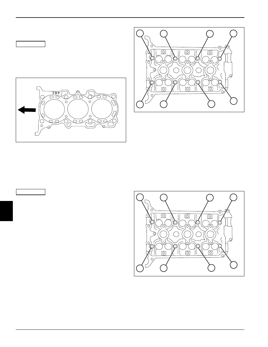
Figure 7-65
1.
Clean cylinder head and cylinder block mating
surfaces. Place head gasket on cylinder block with
forked end toward the front of the engine (arrow).
2.
Install cylinder head using care to align dowel pins.
3.
Apply oil to cylinder head cap screw threads and
seating faces and install. Do not tighten at this time.
IMPORTANT
If the cylinder head, cylinder block, or the cylinder
head cap screw have been replaced, go to step 4.
If installing previously removed parts, go to step 5.
Figure 7-66
4.
Torque the cap screws in sequence to 22 lb-ft (30
N•m).
• Set torque wrench to 35 lb-ft (47 N•m) and repeat
torque sequence.
• Reverse the torque sequence and loosen all cap
screws.
• Re-torque cap screws in sequence to 35 lb-ft
(47 N•m).
• Torque cap screws (1 through 8) in sequence to final
specification.
Cylinder Head Cap Screw Torque: 43.5 lb-ft (59 N•m)
Figure 7-67
5.
Tighten cap screws (1 through 8) in sequence, to
specification.
Cylinder Head Cap Screw Torque: 43.5 lb-ft (59 N•m)
TN0413
TN0403
1
2
3
4
5
6
7
8
TN0403
1
2
3
4
5
6
7
8
REPAIR
7-27
7
Valves
Disassembly
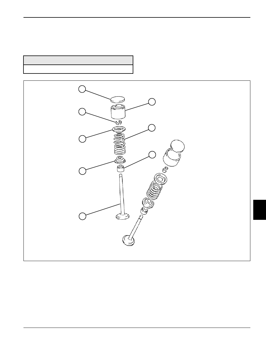
Figure 7-68
1.
Remove shims (1) and tappets (2).
2.
Using a valve spring compressor, remove retainer
locks (8).
3.
Release valve spring compressor and remove
valve (5).
4.
Remove valve spring retainer (7), valve spring (3),
valve seal (4), and valve spring seat (6).
5.
Inspect all parts for wear or damage. (See
“Inspection” on page 7-28.)
Required Tools
Valve Spring Compressor
TN0492
6
8
1
5
3
4
2
7

7-28
REPAIR
7
Inspection
Valves
Figure 7-69
1.
Clean and inspect intake (5) and exhaust (4) valves,
valve stems (3), valve stem tips (1), and retainer lock
grooves (2).
2.
Using a micrometer, measure the valve stem (3) OD.
3.
Using an inside micrometer, measure the ID of valve
guide.
Compare valve stem OD measurement to valve
guide ID measurement. Calculate clearance and
replace as needed.
Valve Guide to Valve Stem Clearance, Intake:
0.0007—0.0018 in. (0.020—0.047 mm)
Valve Guide to Valve Stem Clearance Limit, Intake:
0.002 in (0.07 mm)
Valve Guide to Valve Stem Clearance, Exhaust:
0.0017—0.0028 in. (0.045—0.072 mm)
Valve Guide to Valve Stem Clearance Limit, Exhaust:
0.003 in. (0.09 mm)
Valve Springs
Figure 7-70
Figure 7-71
1.
Measure the free length of valve springs using a
veneer caliper (1). Compare measurement to
specification. Replace as needed.
Valve Spring Free Length: 1.35 in. (34.3 mm)
TN0506
1
3
3
1
2
2
4
5
Required Tools
Veneer Caliper
Spring Compression Gauge
Square
TN0558, 0559
1
2
TN0760
3
4
REPAIR
7-29
7
2.
Using a spring compression gauge (2), compress the
valve spring to 1.17 in. (29.9 mm). Compare the
tension reading to specification and replace as
needed.
Pound Force at 1.17 in. (29.9 mm) Height:
Valve Spring Tension Standard: 22—26 lb-ft
(100—116 N•m)
Valve Spring Tension Limit: 20 lb-ft (88 N•m)
3.
Using a square (4), check valve spring right angle.
Use a feeler gauge to measure distance (3).
Compare measurement to specification. Replace as
needed.
Valve Spring Right Angle Range: 0.000—0.059 in.
(0.00—1.5 mm)
Installation Notes
Always use new O-rings, gaskets, and seals.
Apply clean engine oil to tappet and valve stem contact
surfaces.
Install valve assemblies with new valve seals by reversing
the order of removal.
Check valve clearance. (See “Valve Clearance Check
and Adjustment” on page 5-3.)
Нет комментариевНе стесняйтесь поделиться с нами вашим ценным мнением.
Текст