Suzuki: Engine K6A-YH6. Manual — part 19
7-30
REPAIR
7
7.7 Lubrication System
Dipstick Tube
Removal and Installation
Figure 7-72
1.
Remove nut (1).
2.
Remove dipstick tube (2) and O-ring (3).
3.
Inspect dipstick tube and O-ring. Replace as needed.
Installation Notes
Always use new O-rings, gaskets, and seals.
Install dipstick tube by reversing the order of removal.
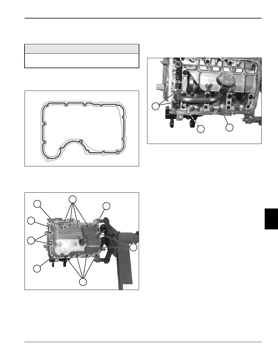
Oil Pan
Removal
Figure 7-73
1.
Drain engine oil. (See “Change Engine Oil” on
page 3-2.)
2.
Remove twelve cap screws (2), three nuts (1), and oil
pan (3).
3.
Inspect oil pan. Replace as needed.
TN0713
1
2
3
TN0741
1
1
1
2
2
2
2
3
REPAIR
7-31
7
Installation
1.
Clean cylinder block, front cover, and oil pan mating
surfaces.
Figure 7-74
2.
Apply Three Bond™ 1215 Sealant to the oil pan
mating surface as shown.
Figure 7-75
3.
Install oil pan (3) using three nuts (1) and twelve cap
screws (2). Tighten to specification.
Oil Pan Torque: 97 lb-in. (11 N•m)
4.
Fill engine oil. (See “Change Engine Oil” on
page 3-2.)
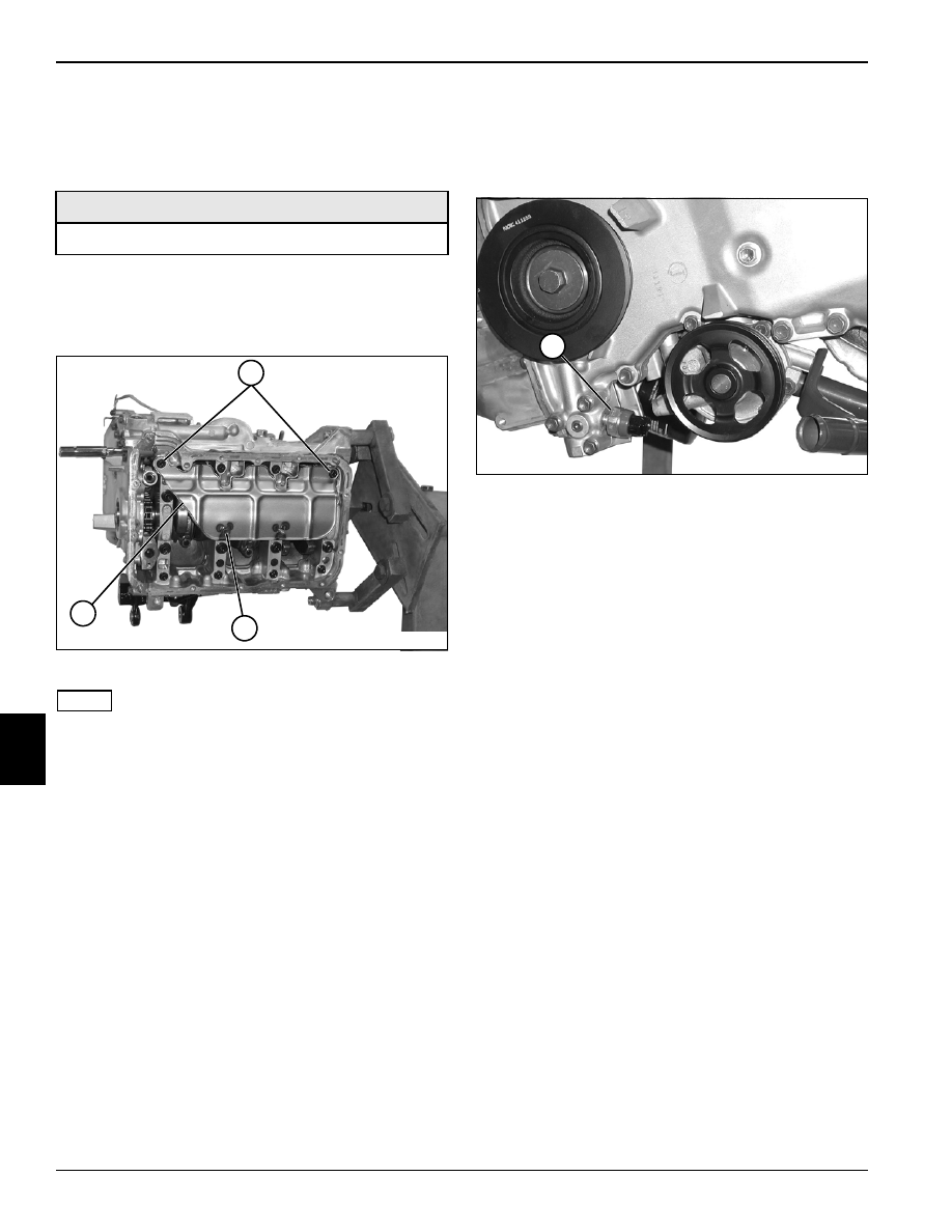
Oil Pump Pickup
Removal and Installation
Figure 7-76
1.
Remove oil pan. (See “Oil Pan” on page 7-30.)
2.
Remove cap screws (1), oil pump pickup (2), and
O-ring (3).
3.
Inspect oil pump pickup and O-ring. Replace as
needed.
Installation Notes
Always use new O-rings, gaskets, and seals.
Install oil pump pickup with new O-ring by reversing the
order of removal.
Install oil pan. (See “Oil Pan” on page 7-30.)
Required Materials
Three Bond™ 1215 (Suzuki PN 99000-1080-15A) or
equivalent
TN0397
TN0741
1
1
1
2
2
2
2
3
TN0742
1
2
3
7-32
REPAIR
7
Crankshaft Baffle
Removal and Installation
1.
Remove oil pan. (See “Oil Pan” on page 7-30.)
2.
Remove oil pump pickup. (See “Oil Pump Pickup” on
page 7-31.)
Figure 7-77
NOTE
Cap screws (1) require the use of a 12-point 8 mm
socket.
3.
Remove cap screws (1 and 2) and crankshaft
baffle (3).
Installation Notes
Install crankshaft baffle by reversing the order of removal.
Install oil pump pickup. (See “Oil Pump Pickup” on
page 7-31.)
Install oil pan. (See “Oil Pan” on page 7-30.)
Oil Pressure Sending Unit
Removal and Installation
Figure 7-78
1.
Remove oil pressure sending unit (1).
2.
Inspect oil pressure sending unit. Replace as
needed.
Installation Notes
Apply thread sealant to the oil pressure sending unit
before installation.
Install oil pressure sending unit by reversing the order of
removal.
Required Tools
12-Point 8 mm Socket
TN0743
3
2
1
TN0715
1
REPAIR
7-33
7
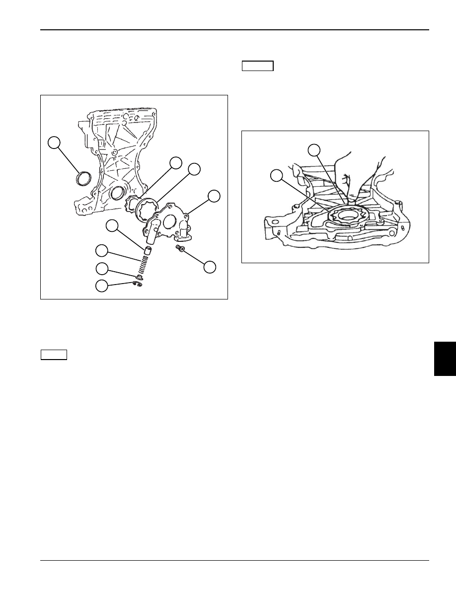
Oil Pump
Removal
Figure 7-79
1.
Remove front cover. (See “Front Cover” on
page 7-12.)
2.
Remove seven screws (5) and oil pump housing (4).
NOTE
Mark inner and outer rotor before removal to aid during
installation.
3.
Remove inner rotor (2) and outer rotor (3).
4.
Remove oil seal (1).
5.
Remove circlip (6), retainer (7), spring (8), and relief
valve (9).
6.
Inspect parts and replace as needed. (See
“Inspection” on page 7-33.)
Inspection
NOTES
Clean engine oil from oil pump rotor bore, and inner and
outer rotors, before performing measurements.
Outer Rotor Radial Clearance
Figure 7-80
1.
Using a feeler gauge, measure the clearance
between outer rotor (1) and the oil pump case rotor
bore (2). If the clearance is beyond the service limit,
replace the oil pump assembly.
Oil Pump Radial Clearance Limit:
0.0004—0.006 in. (0.10—0.15 mm)
TN0557
1
2
3
4
5
6
9
8
7
TN0391
1
2
Нет комментариевНе стесняйтесь поделиться с нами вашим ценным мнением.
Текст