Suzuki Grand Vitara JB416 / JB420. Manual — part 194
3D-2 Propeller Shaft:
Diagnostic Information and Procedures
Propeller Shaft Symptom Diagnosis
S5JB0A3404001
Repair Instructions
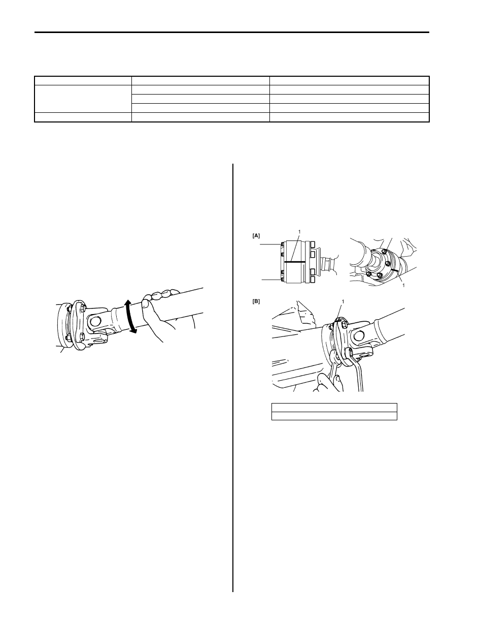
Propeller Shaft Joint Check
S5JB0A3406001
If universal joints and ball joints are suspected of
producing chattering or rattling noise, inspect them for
wear. For universal joint, check to see if cross spider
rattles in yokes or if splines are worn down and replace
defective propeller shaft assembly with new one.
Noise coming from universal joint and ball joint can be
easily distinguished from other noises because rhythm
of chattering or rattling is in step with cruising speed.
Noise is pronounced particularly on standing start or in
coasting condition (when braking effect of engine is
showing in the drive line).
Propeller Shaft Removal and Installation
S5JB0A3406002
Removal
1) Hoist vehicle.
2) Give match marks (1) on joint flange and propeller
shaft as shown in the figure.
3) Remove propeller shaft.
Condition
Possible cause
Correction / Reference Item
Abnormal noise
Loose propeller shaft flange bolt and nut Tighten propeller shaft flange bolt and nut.
Spider bearing worn out or stuck
Replace.
Wear spider
Replace propeller shaft.
Vibration
Deformed propeller shaft
Replace.
I5JB0A340003-01
[A]: Front propeller shaft
[B]: Rear propeller shaft
I5JB0A340002-02

Propeller Shaft: 3D-3
Installation
Reverse removal procedure to install propeller shaft
noting the following points.
• Clean and inspect sliding portion of propeller shaft
end (where oil seal contacts) before installation and if
even small dent or scratch exists, correct end clean it
again.
Then apply grease inside splines of propeller shaft.
“B”: Grease 99000–25010 (SUZUKI Super Grease
A)
• Install propeller shaft aligning match marks.
Otherwise, vibration may occur during driving.
• Use the following specification to torque universal joint
flange nuts and bolts. For front propeller shaft flange
bolt (front differential side), apply thread lock cement
to thread part of bolts if reused.
“A”: Thread lock cement 99000–32110 (Thread
Lock Cement Super 1322)
Tightening torque
Front propeller shaft flange bolt (a): 30 N·m (3.0
kgf-m, 22.0 lb-ft)
Rear propeller shaft flange nut (b): 85 N·m (8.5
kgf-m, 61.5 lb-ft)
Propeller Shaft Disassembly and Assembly
S5JB0A3406005
CAUTION
!
Never disassemble each joint.
Performing this prohibited service will affect
its original performance.
Disassembly
1) Give match marks (1) on flange yoke and shaft as
shown in the figure.
2) Using snap ring plier (1), remove 2 circlips.
[A]: Front propeller shaft
[B]: Rear propeller shaft
IYSQ01521009-01
I5JB0A340004-01
I5JB0A340007-01
I5JB0A340005-02

3D-4 Propeller Shaft:
3) Using special tool, push spider bearing race out 3 –
4 mm (0.12 – 0.16 in.) from shaft yoke race.
NOTE
Before pushing it out, apply penetrate
lubricant between bearing race (1) and yoke
race (2).
Special tool
(A): 09926-48010
Spider bearing race installing position (length
“a”)
“a”: 3 – 4 mm (0.12 – 0.16 in.)
4) Tapping yoke with a hammer, completely remove
bearing race.
5) Take out bearing race on the other side in the same
way as in Step 3) and 4).
6) Push out bearing race on flange yoke side as
described in Step 2) and 3), and then, holding
bearing race in a vise (1), tap flange yoke and take
out race. (Refer to the figure.)
Remove bearing race on the opposite side in the
same way.
NOTE
• Take care not to lose rollers in spider
bearing race when removing it.
• Fit removed bearings temporarily in spider
so that they can be reinstalled in their
original positions.
I5JB0A340006-01
IYSQ01340007-01
IYSQ01340008-01

Propeller Shaft: 3D-5
Assembly
NOTE
Make sure that rollers inside spider bearing
race are all in place.
CAUTION
!
In assembly, be sure to use new circlips,
spider (1) and bearings (2). Reuse of circlips,
spider (1) and bearings (2) once assembled is
prohibited.
1) Make sure to apply grease to spider bearing race.
“A”: Grease 99000–25030 (SUZUKI Super
Grease C)
2) Insert bearing race into yoke, using press, until it is
flush with yoke face. When doing this, insert spider
into bearing race to prevent rollers in bearing race
from coming out.
3) Aligning match marks (1) and insert the other
bearing race on the opposite side into yoke, using
press until it is flush with yoke face.
4) Insert bearing races on the flange yoke side in the
same way as described in Step 1) and 2).
5) Securely fit 4 circlips to shaft and flange yoke.
NOTE
• Make sure that each circlip is fitted in
groove securely.
6) After assembly, check to ensure that both shaft yoke
and flange yoke move smoothly.
Propeller Shaft Inspection
S5JB0A3406004
Inspect propeller shaft, universal joint and ball joint for
damage, and propeller shaft for runout.
If damage is found or shaft runout exceeds its limit,
replace.
Propeller shaft runout
Limit: 0.8 mm (0.031 in.)
IYSQ01340010-01
IYSQ01340009-01
I5JB0A340007-01
IYSQ01340013-01
Нет комментариевНе стесняйтесь поделиться с нами вашим ценным мнением.
Текст