Suzuki Grand Vitara JB416 / JB420. Manual — part 195
3D-6 Propeller Shaft:
Specifications
Tightening Torque Specifications
S5JB0A3407001
NOTE
The specified tightening torque is also described in the following.
“Propeller Shaft Construction”
Reference:
For the tightening torque of fastener not specified in this section, refer to “Fastener Information in Section 0A”.
Special Tools and Equipment
Recommended Service Material
S5JB0A3408001
NOTE
Required service material is also described in the following.
“Propeller Shaft Construction”
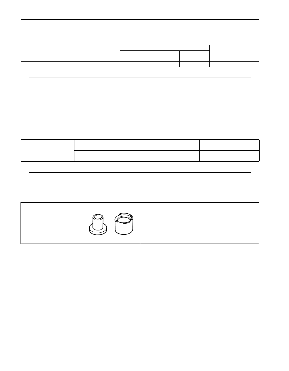
Special Tool
S5JB0A3408002
Fastening part
Tightening torque
Note
N
⋅m
kgf-m
lb-ft
Front propeller shaft flange bolt
30
3.0
22.0
Rear propeller shaft flange nut
85
8.5
61.5
Material
SUZUKI recommended product or Specification
Note
Grease
SUZUKI Super Grease A
P/No.: 99000–25010
SUZUKI Super Grease C
P/No.: 99000–25030
Thread lock cement
Thread Lock Cement Super 1322
P/No.: 99000–32110
09926–48010
Universal joint assembling
tool
)
Table of Contents 4- i
4
Section 4
CONTENTS
Brakes
Precautions . . . . . . . . . . . . .4-1
Precautions. . . . . . . . . . . . . . . . 4-1
Precautions for Brakes. . . . . . . . . . .. 4-1
Brake Control System and Diagnosis ... 4A-1
General Description . . . . . . . . . . . .4A-1
Brakes Construction. . . . . . . . . . . 4A-1
Front Brake Hose / Pipe Construction. . . . . 4A-2
Rear Brake Hose / Pipe Construction . . . . . 4A-3
Master Cylinder Assembly Construction . . . . 4A-3
Booster Assembly Construction . . . . . . .. 4A-4
Diagnostic Information and Procedures. . . 4A-4
Brake Diagnosis Note . . . . . . . . . . . 4A-4
Brakes Symptom Diagnosis. . . . . . . . 4A-5
Repair Instructions . . . . . . . . . . . ..4A-7
Excessive Pedal Travel Check. . . . . . . 4A-7
Brake Pedal Play Check . . . . . . . . . . 4A-7
Brake Fluid Level Check . . . . . . . . . . 4A-7
Air Bleeding of Brake System . . . . . . . . 4A-8
Brake Pedal Free Height Adjustment. . . . .. 4A-9
Brake Light Switch Adjustment . . . . . . ... 4A-9
Brake Flexible Hose and Pipe Check. . . . .. 4A-9
Master Cylinder Check. . . . . . . . . ..4A-10
Flushing Brake Hydraulic System . . . . . . 4A-10
Booster Operation Check. . . . . . . . .. 4A-10
Front Brake Hose / Pipe Removal and
Installation. . . . . . . . . . . . . ...4A-11
Rear Brake Hose / Pipe Removal and
Installation. . . . . . . . . . . . . ...4A-11
Master Cylinder Components. . . . . . . 4A-12
Master Cylinder Reservoir Removal and
Installation. . . . . . . . . . . . . ...4A-13
Master Cylinder Assembly Removal and
Installation. . . . . . . . . . . . . ...4A-14
Master Cylinder Assembly Inspection . . . ...4A-15
Brake Booster Components. . . . . . . .. 4A-16
Brake Booster Removal and Installation . . ... 4A-17
Booster Push Rod Clevis Adjustment . . . ...4A-17
Specifications. . . . . . . . . . . . . .4A-18
Tightening Torque Specifications. . . . . ..4A-18
Special Tools and Equipment . . . . . . ...4A-18
Recommended Service Material. . . . . ... 4A-18
Special Tool . . . . . . . . . . . . . ..4A-18
Front Brakes . . . . . . . . . . . 4B-1
General Description . . . . . . . . . . . .4B-1
Front Disc Brake Caliper Assembly
Construction . . . . . . . . . . . . . ..4B-1
Repair Instructions . . . . . . . . . . . ..4B-2
Front Disc Brake Components . . . . . . . 4B-2
Front Disc Brake Pad On-Vehicle Check . . . 4B-3
Front Disc Brake Pad Removal and
Installation . . . . . . . . . . . . . . .4B-3
Front Brake Disc and Pad Inspection. . . . ..4B-4
Front Disc Brake Caliper Removal and
Installation . . . . . . . . . . . . . . .4B-5
Front Disc Brake Caliper Disassembly and
Assembly. . . . . . . . . . . . . . ...4B-6
Front Disc Brake Caliper Inspection. . . . . 4B-7
Front Brake Disc Removal and Installation . . .4B-8
Front Brake Disc Inspection . . . . . . . . 4B-8
Specifications. . . . . . . . . . . . . ...4B-9
Tightening Torque Specifications. . . . . . 4B-9
Special Tools and Equipment . . . . . . . .4B-9
Recommended Service Material . . . . . . .4B-9
Rear Brakes. . . . . . . . . . . .. 4C-1
General Description . . . . . . . . . . . .4C-1
Rear Drum Brake Assembly Construction . . ..4C-1
Repair Instructions . . . . . . . . . . . ..4C-2
Rear Drum Brake Assembly Components . . ..4C-2
Rear Brake Drum Removal and Installation. . 4C-3
Rear Brake Drum and Shoe Inspection . . . ..4C-4
Rear Brake Shoe On-Vehicle Check. . . . ...4C-4
Rear Brake Shoe Removal and Installation . . 4C-5
Rear Brake Shoe Inspection . . . . . . . ...4C-6
Wheel Cylinder Removal and Installation . . ...4C-6
Wheel Cylinder Inspection . . . . . . . . ..4C-7
Rear Brake Back Plate Removal and
Installation . . . . . . . . . . . . . . .4C-7
Specifications. . . . . . . . . . . . . ...4C-9
Tightening Torque Specifications. . . . . . 4C-9
Special Tools and Equipment . . . . . . . .4C-9
Recommended Service Material . . . . . . .4C-9
Parking Brake . . . . . . . . . . .. 4D-1
Component Location . . . . . . . . . . ...4D-1
4-ii Table of Contents
Parking Brake Check and Adjustment . . . . 4D-2
Parking Brake Lever Removal and Installation . 4D-3
Parking Brake Cable Removal and
Installation. . . . . . . . . . . . . . .4D-3
Specifications. . . . . . . . . . . . . ...4D-4
Tightening Torque Specifications. . . . . . 4D-4
ABS. . . . . . . . . . . . . . . 4E-1
Precautions. . . . . . . . . . . . . . ...4E-1
Precautions in Diagnosing Troubles . . . . ...4E-1
Precautions in On-Vehicle Service. . . . . ..4E-1
General Description . . . . . . . . . . . .4E-1
ABS Description . . . . . . . . . . . . ..4E-1
ABS Hydraulic Unit / Control Module
Assembly Description . . . . . . . . . ...4E-2
CAN Communication System Description. . ...4E-2
Schematic and Routing Diagram. . . . . . 4E-3
ABS Schematic . . . . . . . . . . . . ...4E-3
ABS Wiring Circuit Diagram . . . . . . . . 4E-4
Component Location . . . . . . . . . . ...4E-6
ABS Components Location . . . . . . . . .4E-6
Diagnostic Information and Procedures. . . 4E-7
ABS Check. . . . . . . . . . . . . . ..4E-7
ABS Warning Lamp Check . . . . . . . . .4E-9
EBD Warning Lamp (Brake Warning Lamp)
Check. . . . . . . . . . . . . . . . 4E-9
DTC Check. . . . . . . . . . . . . . 4E-10
DTC Table. . . . . . . . . . . . . . .4E-10
DTC Clearance . . . . . . . . . . . . .4E-11
Scan Tool Data . . . . . . . . . . . . .4E-11
ABS Warning Lamp Does Not Come ON at
Ignition Switch ON . . . . . . . . . . ..4E-12
ABS Warning Lamp Comes ON Steady. . . 4E-14
ABS Warning Lamp Flashes Continuously
while Ignition Switch Is ON . . . . . . . .4E-16
EBD Warning Lamp (Brake Warning Lamp)
Comes ON Steady . . . . . . . . . . ..4E-17
Serial Data Link Circuit Check . . . . . . ..4E-18
DTC C1015: G Sensor Circuit. . . . . . ...4E-20
DTC C1021, C1022 / C1025, C1026 / C1031,
DTC C1041 / C1045 / C1051 / C1055, C1042
DTC C1057: Power Source Circuit . . . . ...4E-24
DTC C1061: ABS Pump Motor and/or Motor
Driver Circuit . . . . . . . . . . . . ...4E-25
DTC C1063: Solenoid Valve Power Supply
Driver Circuit . . . . . . . . . . . . ...4E-26
DTC C1071: ABS Control Module. . . . . .4E-27
DTC U1073: Control Module Communication
Bus Off . . . . . . . . . . . . . . . 4E-28
DTC U1100: Lost Communication with ECM
(Reception Error). . . . . . . . . . . .4E-30
Repair Instructions . . . . . . . . . . . 4E-31
ABS Hydraulic Unit Operation Check. . . . 4E-31
ABS Hydraulic Unit / Control Module
Assembly Components . . . . . . . . ...4E-32
ABS Hydraulic Unit / Control Module
Assembly On-Vehicle Inspection . . . . . 4E-32
ABS Hydraulic Unit / Control Module
Assembly Removal and Installation . . . . 4E-33
Front Wheel Speed Sensor On-Vehicle
Inspection. . . . . . . . . . . . . . 4E-35
Front Wheel Speed Sensor Removal and
Installation . . . . . . . . . . . . . ...4E-36
Front Wheel Speed Sensor Inspection . . . .4E-37
Rear Wheel Speed Sensor On-Vehicle
Inspection. . . . . . . . . . . . . . 4E-37
Rear Wheel Speed Sensor Removal and
Installation . . . . . . . . . . . . . ...4E-37
Installation . . . . . . . . . . . . . ...4E-38
Rear Wheel Encoder On-Vehicle Inspection. .4E-38
Rear Wheel Encoder Removal and
Installation . . . . . . . . . . . . . ...4E-38
Specifications . . . . . . . . . . . . . .4E-39
Tightening Torque Specifications. . . . . ..4E-39
Precautions: 4-1
Brakes
Precautions
Precautions
Precautions for Brakes
S5JB0A4000001
Suspension Caution
Refer to “Suspension Caution in Section 00”.
Wheels and Tires Caution
Refer to “Wheels and Tires Caution in Section 00”.
Brake Caution
Refer to “Brakes Caution and Note in Section 00”.
General Precautions
Refer to “General Precautions in Section 00”.
Vehicle Lifting Points
Refer to “Vehicle Lifting Points in Section 0A”.
Fastener Caution
Refer to “Fastener Caution in Section 00”.
Fastener Information
Refer to “Fastener Information in Section 0A”.
Нет комментариевНе стесняйтесь поделиться с нами вашим ценным мнением.
Текст