Suzuki Grand Vitara JB416 / JB420. Manual — part 193
3C-86 Transfer: Non-Shift Type (Transfer without Shift Actuator)
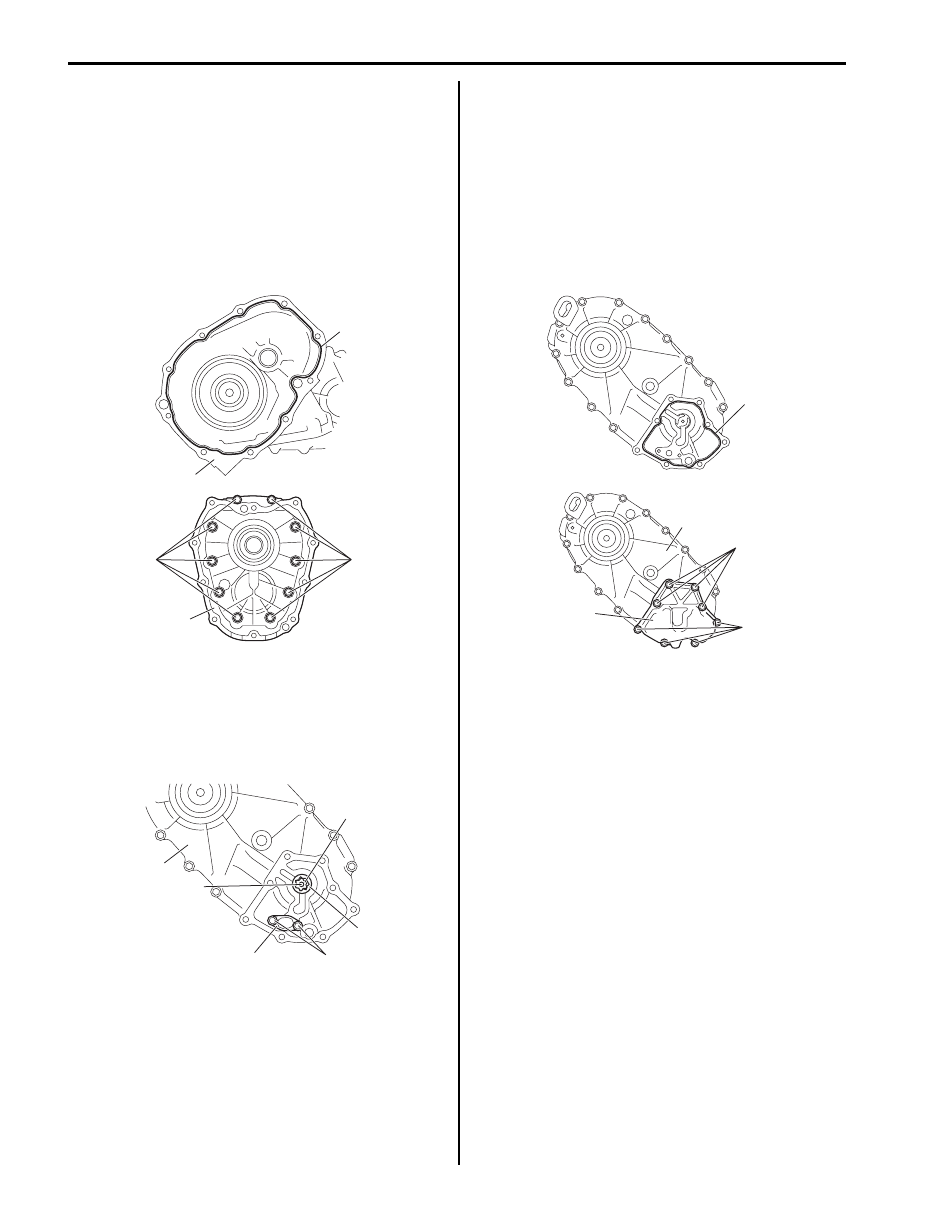
19) Clean mating surface of both center case (1) and
front case, apply sealant to center case as shown in
figure by such amount that its section is 1.2 mm
(0.047 in.) in diameter, mate front case (3) with
center case and then tighten bolts (2) to specified
torque.
“A”: Sealant 99000–31260 (SUZUKI Bond
No.1217G)
Tightening torque
Rear case bolt (a): 23 N·m (2.3 kgf-m, 17.0 lb-ft)
20) Install oil strainer (1) to rear case (2).
Tightening torque
Strainer bolt (a): 10 N·m (1.0 kgf-m, 7.5 lb-ft)
21) Install oil pump inner rotor (3), outer rotor (4) and
drive pin (5) to rear case.
22) Clean mating surface of oil pump cover (1) and rear
case (2), apply sealant to rear case as shown in
figure by such amount that its section is 1.2 mm
(0.047 in.) in diameter, mate oil pump cover with rear
case and then tighten bolts (3) to specified torque.
“A”: Sealant 99000–31260 (SUZUKI Bond
No.1217G)
Tightening torque
Oil pump cover bolt (a): 23 N·m (2.3 kgf-m, 17.0
lb-ft)
“A”
1
2, (a)
2, (a)
3
I5JB0A331102-02
2
5
1
(a)
4
3
I5JB0A331103-01
“A”
3, (a)
3, (a)
1
2
I5JB0A331104-01

Transfer: Non-Shift Type (Transfer without Shift Actuator) 3C-87
23) Clean mating surface of differential lock shift lever
case (1) and center case (5), apply sealant to center
case as shown in figure by such amount that its
section is 1.2 mm (0.047 in.) in diameter, confirm the
each fork of lever case is in groove of the sleeve,
mate differential lock shift lever case with center
case and then tighten differential lock shift lever case
bolts (3) to which thread lock cement has been
applied and differential lock shift lever case dowel
bolts (4) to specified torque.
“A”: Sealant 99000–31260 (SUZUKI Bond
No.1217G)
“B”: Thread lock cement 99000–32110 (Thread
Lock Cement Super 1322)
Tightening torque
Differential lock shift lever case bolt (a): 23 N·m
(2.3 kgf-m, 17.0 lb-ft)
Differential lock shift lever case dowel bolt (b):
23 N·m (2.3 kgf-m, 17.0 lb-ft)
Input Gear Assembly Disassembly and
Reassembly
S5JB0A3326008
Front Output Shaft Assembly Disassembly and
Reassembly
S5JB0A3326009
Rear Output Shaft Assembly Disassembly and
Reassembly
S5JB0A3326010
“A”
2
1
3, “B”, (a)
3, “B”, (a)
4, (b)
I5JB0A331105-03
3C-88 Transfer: Non-Shift Type (Transfer without Shift Actuator)
Specifications
Tightening Torque Specifications
S5JB0A3327001
NOTE
The specified tightening torque is also described in the following.
“Transfer Assembly Components: Non-Shift Type (Transfer without Shift Actuator)”
Reference:
For the tightening torque of fastener not specified in this section, refer to “Fastener Information in Section 0A”.
Special Tools and Equipment
Recommended Service Material
S5JB0A3328001
NOTE
Required service material is also described in the following.
“Transfer Assembly Components: Non-Shift Type (Transfer without Shift Actuator)”
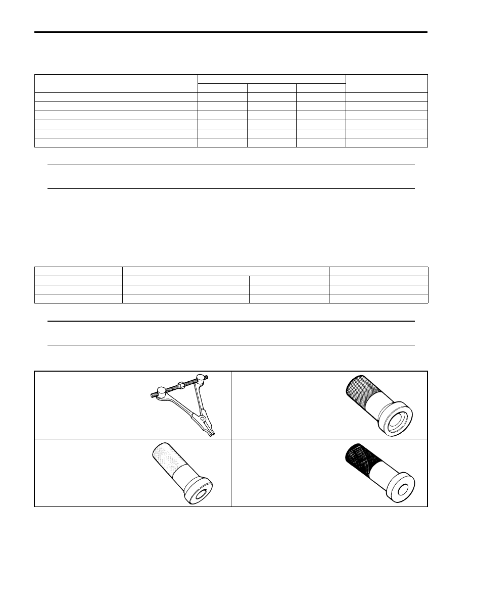
Special Tool
S5JB0A3328002
Fastening part
Tightening torque
Note
N
⋅m
kgf-m
lb-ft
Input gear plate bolt
23
2.3
17.0
Rear case bolt
23
2.3
17.0
Strainer bolt
10
1.0
7.5
Oil pump cover bolt
23
2.3
17.0
Differential lock shift lever case bolt
23
2.3
17.0
Differential lock shift lever case dowel bolt
23
2.3
17.0
Material
SUZUKI recommended product or Specification
Note
Grease
SUZUKI Super Grease A
P/No.: 99000–25010
Sealant
SUZUKI Bond No.1217G
P/No.: 99000–31260
Thread lock cement
Thread Lock Cement Super 1322
P/No.: 99000–32110
09912–34510
09913–70123
Case separator
Bearing installing tool
09913–76010
09913–85210
Bearing installer
Bearing installer
Propeller Shaft: 3D-1
Driveline / Axle
Propeller Shaft
Precautions
Propeller Shaft Caution
S5JB0A3400001
CAUTION
!
• All propeller shaft fasteners are an important attaching part in that it could affect the performance of
vital parts and systems, and/or could result in major repair expense. They must be replaced with one
of the same part number or with an equivalent part if replacement becomes necessary. Do not use a
replacement part of lesser quality or substitute design. Torque values must be used as specified
during reassembly to assure proper retention of this part.
• Never attempt to heat, quench or straighten any propeller shaft part. Replace it with a new part, or
damage to the part may result.
General Description
Propeller Shaft Construction
S5JB0A3401001
Most universal joints and ball joints require no maintenance. They are lubricated for life and can not be lubricated on
the vehicle. If a universal joint becomes noisy or worn, it must be replaced.
The propeller shaft is a balanced unit. Handle it carefully so that balance can be maintained.
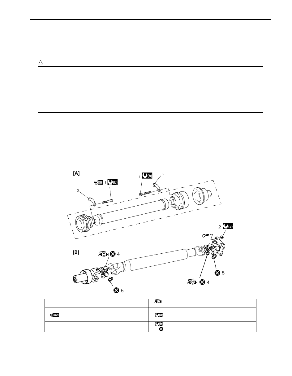
I5JB0A340001-02
[A]: Front propeller shaft
4. Spider joint assembly
: Apply grease (99000-25030) to spider bearing race.
[B]: Rear propeller shaft
5. Circlip
1. Front propeller shaft flange bolt
: Apply thread lock 99000-32110 to bolt thread.
: 85 N
⋅m (8.5 kgf-m, 61.5 lb-ft)
2. Rear propeller shaft flange nut
: 30 N
⋅m (3.0 kgf-m, 22.0 lb-ft)
3. Support washer
: Do not reuse.
Нет комментариевНе стесняйтесь поделиться с нами вашим ценным мнением.
Текст