Suzuki Grand Vitara JB416 / JB420. Manual — part 29
1A-65 Engine General Information and Diagnosis:
DTC P0030: HO2S Heater Control Circuit (Sensor-1)
S5JB0A1104088
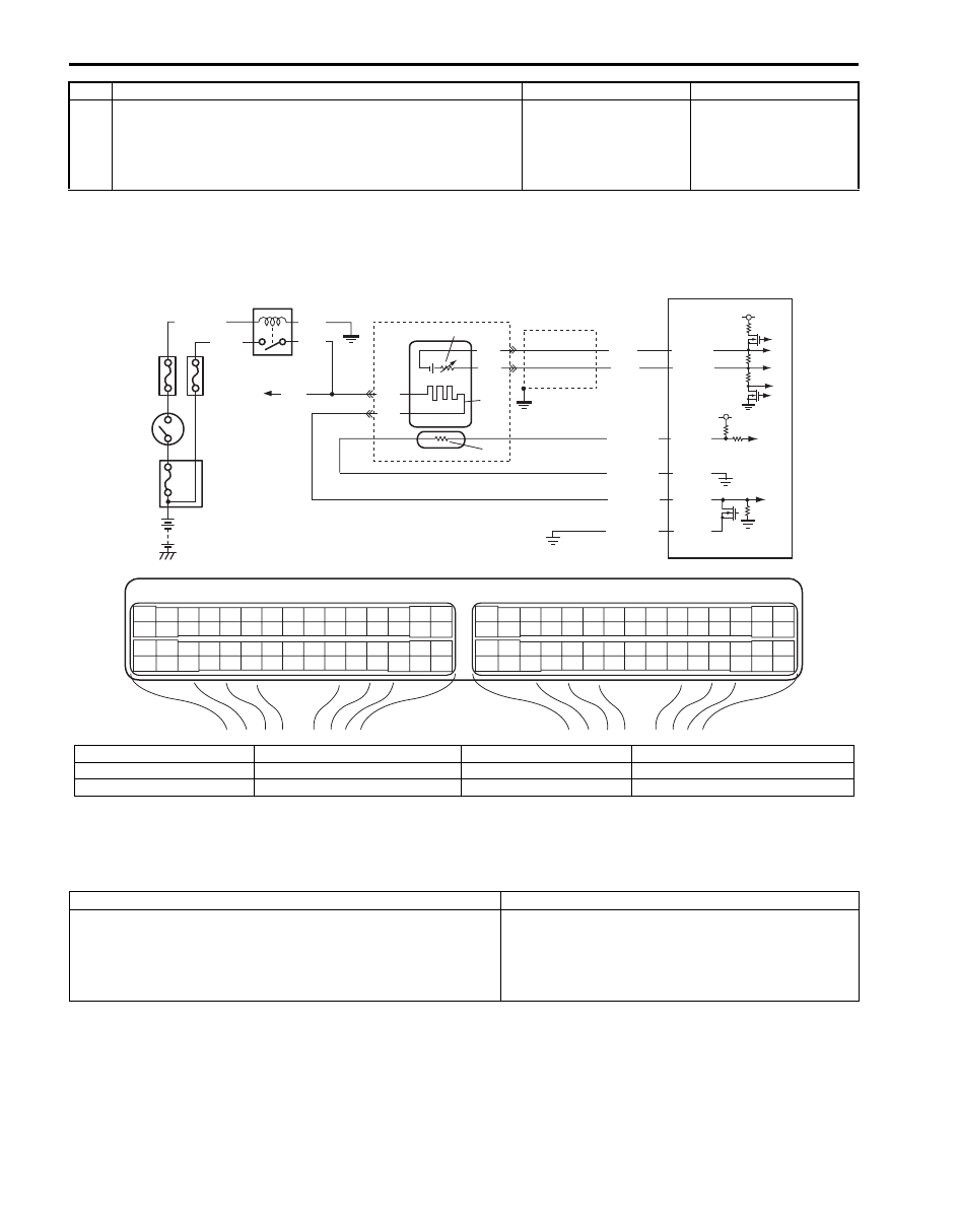
Wiring Diagram
A/F Sensor Description
Refer to “A/F Sensor Description”.
DTC Detecting Condition and Trouble Area
DTC Confirmation Procedure
1) With ignition switch turned OFF, connect scan tool.
2) Turn ON ignition switch and clear DTC using scan tool.
3) Start engine and warm up to normal operating temperature.
4) Run engine at idle speed for 4 min. or more.
5) Check DTC and pending DTC.
8
Oil control valve check
1) Check oil control valve referring to “Oil Control Valve
Inspection: For M16A Engine with VVT in Section 1D”.
Is it in good condition?
Replace camshaft
timing sprocket.
Replace oil control
valve.
Step
Action
Yes
No
E23
C37
3
4
18
19
5
6
7
10
11
17
20
47
46
49
50
51
21
22
52
16
25
9
24
14
29
55
57
54 53
59
60
58
2
26
27
28
15
30
56
48
32
31
34
35
36
37
40
42
39 38
44
45
43
41
33
1
12
13
23
8
3
4
18
19
5
6
7
10
11
17
20
47
46
49
50
51
21
22
52
16
25
9
24
14
29
55
57
54 53
59
60
58
2
26
27
28
15
30
56
48
32
31
34
35
36
37
40
42
39 38
44
45
43
41
33
1
12
13
23
8
4
3
9
PNK
6
2
1
8
5
BLK/WHT
BLK
PNK
*GRN
C37-34
C37-32
C37-37
C37-38
BLK
BLK
BLU
WHT
C37-35
C37-31
WHT
BLK
RED/YEL
RED/BLU
PNK/BLU
BLK/YEL
10
7
11
5 V
5 V
I5JB0A110027-02
1. HO2S heater relay
4. “O2 HTR” fuse
7. Heater
10. Adjusting resistor
2. Shield wire
5. “IG COIL” fuse
8. To HO2S-2 heater
11. Sensor
3. Ignition switch
6. A/F sensor
9. ECM
*: For M16 engine
DTC detecting condition
Trouble area
Impedance of A/F sensor element is higher than or lower than
specified range for more than 200 sec. even though A/F sensor
heater is turned ON for more than specified time with engine
running. (A/F sensor does not activate)
(2 driving cycle detection logic)
• A/F sensor heater circuit
• A/F sensor heater
• ECM

Engine General Information and Diagnosis: 1A-66
DTC Troubleshooting
NOTE
Before this trouble shooting is performed, read the precautions for DTC troubleshooting referring to
“Precautions For DTC Troubleshooting”.
DTC P0031 / P0032: HO2S Heater Control Circuit Low / High (Sensor-1)
S5JB0A1104015
Wiring Diagram
Refer to “DTC P0030: HO2S Heater Control Circuit (Sensor-1)”.
A/F Sensor Description
Refer to “A/F Sensor Description”.
DTC Detecting Condition and Trouble Area
Step
Action
Yes
No
1
Was “Engine and Emission Control System Check”
performed?
Go to Step 2.
Go to “Engine and
Emission Control
System Check”.
2
DTC check
Is there any DTC(s) other than P0030?
Go to applicable DTC
diag. flow.
Go to Step 3.
3
Sensor circuit check
1) Disconnect connectors from A/F sensor and ECM with
ignition switch turned OFF.
2) Check for proper connection to A/F sensor terminals and
ECM terminals.
3) If wire and connection are OK, measure each wire
resistance of A/F sensor circuit (sensor and heater)
between A/F sensor connector and ECM connector.
Is each measured wire resistance lower than 1
Ω
?
Go to Step 4.
Repair or replace
defective wire circuit.
4
Sensor circuit insulation check
1) Measure resistance between wire and wire at sensor
circuit terminals of A/F sensor connector (no continuity
check).
Is measured resistance infinity?
Substitute a known
good A/F sensor and
recheck.
Repair or replace
defective circuit.
DTC detecting condition
Trouble area
P0031:
Heater control circuit voltage of A/F sensor is lower than
specification for more than specified time continuously even
though control duty ratio of A/F sensor heater is less than 90%
with engine running. (Heater control duty pulse is not detected
in its circuit of ECM)
(2 driving cycle detection logic)
P0032:
Heater control circuit voltage of A/F sensor is higher than
specification for more than specified time continuously even
though control duty ratio of A/F sensor heater is more than 10%
with engine running. (Heater control duty pulse is not detected
in its circuit of ECM)
(2 driving cycle detection logic)
• A/F sensor heater circuit
• A/F sensor heater
• ECM

1A-67 Engine General Information and Diagnosis:
DTC Confirmation Procedure
1) With ignition switch turned OFF, connect scan tool.
2) Turn ON ignition switch and clear DTC using scan tool.
3) Start engine and warm up to normal operating temperature.
4) Run engine at idle speed for 1 min. or more.
5) Check DTC and pending DTC.
DTC Troubleshooting
NOTE
Before this trouble shooting is performed, read the precautions for DTC troubleshooting referring to
“Precautions For DTC Troubleshooting”.
Step
Action
Yes
No
1
Was “Engine and Emission Control System Check”
performed?
Go to Step 2.
Go to “Engine and
Emission Control
System Check”.
2
A/F sensor heater circuit check
1) Disconnect connector from A/F sensor with ignition
switch turned OFF.
2) Check for proper connection to A/F sensor connector.
3) If connection are OK, measure voltage between heater
power terminal of A/F sensor connector and vehicle
body ground with ignition switch turned ON.
Is measured voltage 10 – 14 V?
Go to Step 9.
Go to Step 3.
3
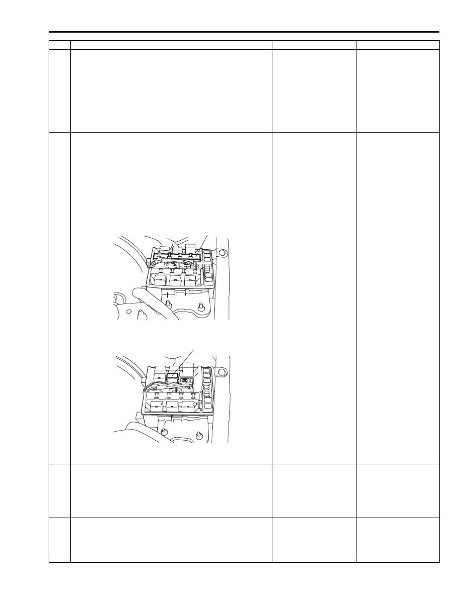
HO2S heater fuse check
1) Check for “O2 HTR” fuse (1) blown.
For J20 engine
For M16 engine
Is “O2 HTR” fuse in good condition?
Go to Step 5.
Go to Step 4.
1
I5JB0A110028-02
1
I5JB0A110029-02
Engine General Information and Diagnosis: 1A-68
4
A/F sensor and HO2S heater resistance check
1) Disconnect connector from HO2S-2 with ignition switch
turned OFF.
2) Check heater resistance of A/F sensor and HO2S
referring to “Air Fuel Ratio (A/F) Sensor On-Vehicle
Inspection in Section 1C” and “Heated Oxygen Sensor
(HO2S-2) Heater On-Vehicle Inspection in Section 1C”.
Are A/F sensor heater and HO2S heater in good condition?
Go to Step 6.
Replace defective
sensor.
5
HO2S heater relay power circuit check
1) Remove integration relay No.2 (for J20 engine) (1) or
HO2S heater relay (for M16 engine) (2) with ignition
switch turned OFF.
2) Check for proper connection to relay connector.
3) If connection are OK, measure voltage between each
relay power terminal of relay connector and vehicle body
ground with ignition switch tuned ON.
For J20 engine
For M16 engine
Is each measured voltage 10 – 14 V?
Go to Step 6.
Power circuit is open.
6
Check HO2S heater relay
1) Check integration relay No.2 (for J20 engine) or HO2S
heater relay (for M16 engine) referring to “Control Relay
Inspection in Section 1C”.
Is it in good condition?
Go to Step 7.
Replace relay.
7
A/F sensor heater circuit check
1) Measure insulation resistance between heater terminals
of A/F sensor connector.
Is measured resistance infinity?
Go to Step 8.
Repair or replace short
wire.
Step
Action
Yes
No
1
I5JB0A110030-02
2
I5JB0A110031-03
Нет комментариевНе стесняйтесь поделиться с нами вашим ценным мнением.
Текст