Suzuki Grand Vitara JB416 / JB420. Manual — part 54

1A-165 Engine General Information and Diagnosis:
DTC Troubleshooting
NOTE
Before this trouble shooting is performed, read the precautions for DTC troubleshooting referring to
“Precautions For DTC Troubleshooting”.
Step
Action
Yes
No
1
Was “Engine and Emission Control System Check”
performed?
Go to Step 2.
Go to “Engine and
Emission Control
System Check”.
2
Generator control circuit check
1) Disconnect connector from generator and ECM with
ignition switch turned OFF.
2) Check for proper connection of wire terminal to
generator connector and to ECM connector.
3) If connections are OK, check generator control
(generator “C” terminal) circuit and field coil monitor
(generator “FR” terminal) circuit for the following.
• Resistance of each generator control wire and field
coil monitor wire between generator connector and
ECM connector is less than 1
Ω (continuity check)
• Resistance between generator control wire and field
coil monitor wire of generator connector is infinity
(insulation check)
• Resistance between each generator control wire and
field coil monitor wire of generator connector and
vehicle body ground is infinity (ground circuit short
check)
• Voltage between each generator control wire and field
coil monitor wire of generator connector and vehicle
body ground is 0 V with ignition switch tuned ON
(power circuit short check)
Are they in good condition?
Go to Step 3.
Repair or replace
defective wire.
3
Generator check
1) Check for generator output referring to “Generator Test
(Undercharged Battery Check) in Section 1J” and
“Generator Inspection in Section 1J”.
Is check result satisfactory?
Substitute a known
good ECM and recheck.
Repair or replace
generator.
Engine General Information and Diagnosis: 1A-166
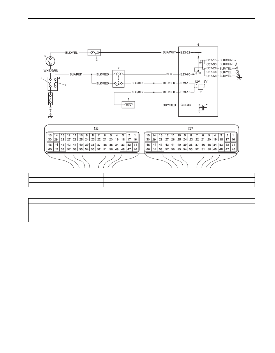
DTC P0660: Intake Manifold Tuning Valve Control Circuit / Open (For J20 Engine)
S5JB0A1104092
Wiring Diagram
DTC Detecting Condition and Trouble Area
DTC Confirmation Procedure
1) With ignition switch OFF, connect scan tool to DLC.
2) Turn ON ignition switch and clear DTC using scan tool.
3) Start engine and warm up normal operating temperature.
4) Run engine at idle speed for 3 min. or more.
5) Check DTC.
I5JB0A110064-02
1. IMT vacuum solenoid valve
4. Fuse box No.2
7. “FI” fuse
2. Main relay
5. Ignition switch
8. “IGN” fuse
3. “IG COIL” fuse
6. ECM
DTC detecting condition
Trouble area
Monitor signal of IMT vacuum solenoid valve is different from
command signal. (Circuit open or short)
(1 driving cycle detection logic but MIL does not light up)
• IMT vacuum solenoid valve
• IMT vacuum solenoid valve circuit
• ECM

1A-167 Engine General Information and Diagnosis:
DTC Troubleshooting
NOTE
Before this trouble shooting is performed, read the precautions for DTC troubleshooting referring to
“Precautions For DTC Troubleshooting”.
Step
Action
Yes
No
1
Was “Engine and Emission Control System Check”
performed?
Go to Step 2.
Go to “Engine and
Emission Control
System Check”.
2
IMT vacuum solenoid valve power supply circuit check
1) Turn OFF ignition switch and disconnect connector from
IMT vacuum solenoid valve.
2) Measure voltage between engine ground and “BLU/
BLK” wire terminal of IMT vacuum solenoid valve
connector with ignition switch turned ON.
Is it voltage 10 – 14 V?
Go to Step 3.
“BLU/BLK” wire is open
circuit.
3
Wire circuit check
1) Disconnect connectors from ECM with ignition switch
turned OFF.
2) Measure resistance between “C37-33” terminal of ECM
connector and vehicle body ground.
Is resistance infinity?
Go to Step 4.
“GRY/RED” wire is
shorted to ground
circuit.
4
Wire circuit check
1) Measure voltage between “C37-33” terminal of ECM
connector and vehicle body ground with ignition switch
turned ON.
Is voltage 0 V?
Go to Step 5.
“GRY/RED” wire is
shorted to other circuit.
5
Wire circuit check
1) Connect connector to IMT vacuum solenoid valve with
ignition switch turned OFF.
2) Turn ON ignition switch and measure voltage between
“C37-33” terminal of ECM connector and vehicle body
ground.
Is it voltage 10 – 14 V?
Go to Step 6.
“GRY/RED” wire is open
circuit.
6
IMT vacuum solenoid valve check
1) Check for coil resistance of IMT vacuum solenoid valve
referring to “Vacuum Tank Assembly Inspection (For J20
Engine) in Section 1C”.
Is it in good condition?
Go to Step 7.
Faulty IMT vacuum
solenoid valve.
7
IMT vacuum solenoid circuit check
1) With ignition switch turn OFF, measure resistance
between “E23-1/16” terminal and “C37-33” terminal of
ECM connector.
Is resistance below 40
Ω
at 20
°
C, 68
°
F?
Faulty ECM. Substitute
a known-good ECM and
recheck.
“GRY/RED” and/or
“BLU/BLK” wire are high
resistance circuit.
Engine General Information and Diagnosis: 1A-168
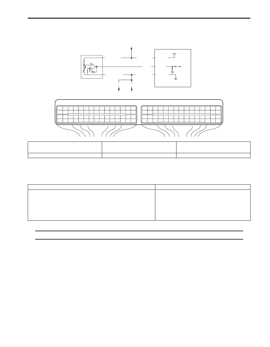
DTC P1501 / P1502: Electric Load Current Sensor Circuit Low / High
S5JB0A1104093
System and Wiring Diagram
Electric Load Current Sensor Description
Refer to “Generator Control System Description”.
DTC Detecting Condition and Trouble Area
NOTE
When DTC P0107 and P0532 are indicated together, it is possible that “GRY/RED” wire circuit open.
DTC Confirmation Procedure
1) With ignition switch turned OFF, connect scan tool to DLC.
2) Turn ON ignition switch and clear DTC.
3) Make sure that all accessory switch is tuned OFF.
4) Start engine and warm it up to normal operating temperature (ECT approx. 90 – 95
°C, 193 – 203 °F).
5) Increase engine speed to 3000 rpm.
6) In this state, Turn ON following accessory switch.
• Head lights switch.
• Blower motor switch (max position).
• Rear defogger switch.
7) Decrease engine speed to idle.
8) Check DTC and pending DTC.
1
C37-9
BLU
GRN
GRY/GRN
GRY/GRN
C37-14
GRY/RED
GRY/RED
E23
C37
3
4
18
19
5
6
7
10
11
17
20
47 46
49
50
51
21
22
52
16
25
9
24
14
29
55
57
54 53
59
60
58
2
26
27
28
15
30
56
48
32 31
34
35
36
37
40
42
39 38
44
45
43
41
33
1
12
13
23
8
3
4
18
19
5
6
7
10
11
17
20
47 46
49
50
51
21
22
52
16
25
9
24
14
29
55
57
54 53
59
60
58
2
26
27
28
15
30
56
48
32 31
34
35
36
37
40
42
39 38
44
45
43
41
33
1
12
13
23
8
GRY/GRN
5V
2
3
4
5
C37-57
I5JB0A110065-01
1. Electric load current sensor
3. To other sensors (MAP, CO adjust resister (if
equipped), A/C refrigerant pressure (if
equipped)
5. To other sensors (IAT, ECT, MAP, CO adjust
resister (if equipped), A/C refrigerant pressure
(if equipped)
2. ECM
4. To HO2S-2
DTC detecting condition
Trouble area
P1501:
Electric load current sensor circuit voltage is lower than specified
range.
P1502:
Electric load current sensor circuit voltage is higher than specified
range.
Electric load current sensor and/or its circuit
ECM
Нет комментариевНе стесняйтесь поделиться с нами вашим ценным мнением.
Текст