Suzuki Grand Vitara JB416 / JB420. Manual — part 55

1A-169 Engine General Information and Diagnosis:
DTC Troubleshooting
NOTE
Before this trouble shooting is performed, read the precautions for DTC troubleshooting referring to
“Precautions For DTC Troubleshooting”.
Step
Action
Yes
No
1
Was “Engine and Emission Control System Check”
performed?
Go to Step 2.
Go to “Engine and
Emission Control
System Check”.
2
Electric load current sensor power/ ground circuit
check
1) Disconnect connector from electric load current sensor
with ignition switch turned OFF.
2) Check for proper connection of wire terminal to electric
load current sensor connector.
3) If connections are OK, check electric load current sensor
circuit for the following.
• Resistance between ground circuit wire of electric
load current sensor connector and vehicle body
ground is less than 1
Ω (ground circuit check)
• Voltage between 5 V power circuit wire of electric load
current sensor connector and vehicle body ground is
4 – 6 V with ignition switch tuned ON (power circuit
check)
Is it in good condition?
Go to Step 3.
Repair or replace
defective wire and/or
check connected
sensors to this circuit.
3
Electric load current sensor output circuit check
1) Disconnect connector from ECM with ignition switch
turned OFF.
2) Check for proper connection of electric load current
sensor wire terminal to ECM connector.
3) If connections are OK, check electric load current sensor
circuit for the following.
• Resistance of electric load current sensor output
circuit wire between electric load current sensor
connector and ECM connector is less than 1
Ω
(continuity check)
• Resistance between electric load current sensor
output circuit wire of electric load current sensor
connector and vehicle body ground is infinity
(insulation check)
• Voltage between electric load current sensor output
circuit wire of electric load current sensor connector
and vehicle body ground is 0 V with ignition switch
tuned ON (power circuit short check)
Is it in good condition?
Go to Step 4.
Repair or replace
defective wire.
4
Electric load current sensor check
1) Check for electric load current sensor output referring to
“Electric Load Current Sensor On-Vehicle Inspection
(For J20 Engine) in Section 1C”.
Is check result satisfactory?
Substitute a known
good ECM and recheck.
Replace electric load
current sensor.
Engine General Information and Diagnosis: 1A-170
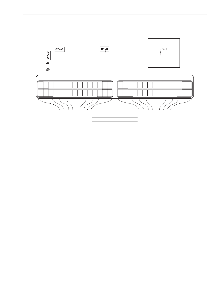
DTC P1510: ECM Back-Up Power Supply Malfunction
S5JB0A1104056
Wiring Diagram
Circuit Description
Battery voltage is supplied so that DTC memory, values for engine control learned by ECM, etc. are kept in ECM even
when the ignition switch is turned OFF.
DTC Detecting Condition and Trouble Area
DTC Confirmation Procedure
1) Connect scan tool to DLC with ignition switch turned OFF.
2) Turn ON ignition switch and clear DTC using scan tool and run engine at idle speed for 1 min.
3) Check DTC and pending DTC.
E23
C37
3
4
18
19
5
6
7
10
11
17
20
47
46
49
50
51
21
22
52
16
25
9
24
14
29
55
57
54 53
59
60
58
2
26
27
28
15
30
56
48
32
31
34
35
36
37
40
42
39 38
44
45
43
41
33
1
12
13
23
8
3
4
18
19
5
6
7
10
11
17
20
47
46
49
50
51
21
22
52
16
25
9
24
14
29
55
57
54 53
59
60
58
2
26
27
28
15
30
56
48
32
31
34
35
36
37
40
42
39 38
44
45
43
41
33
1
12
13
23
8
2
1
E23-2
WHT
WHT
I5JB0A110066-01
1. ECM
2. “DOME” fuse
DTC detecting condition
Trouble area
Back-up power circuit voltage is no inputted for 5 seconds
continuously while engine is running.
(1 driving cycle detection logic)
Battery voltage supply circuit

1A-171 Engine General Information and Diagnosis:
DTC Troubleshooting
NOTE
Before this trouble shooting is performed, read the precautions for DTC troubleshooting referring to
“Precautions For DTC Troubleshooting”.
Step
Action
Yes
No
1
Was “Engine and Emission Control System Check”
performed?
Go to Step 2.
Go to “Engine and
Emission Control
System Check”.
2
Battery voltage supply circuit check
1) Turn OFF ignition switch.
2) Remove ECM from its bracket with ECM connectors
connected.
3) With engine running, measure voltage between “E23-2”
terminal of ECM connector and engine ground.
Is voltage 10 – 14 V?
Poor “E23-2”
connection or
intermittent trouble.
Check for intermittent
referring to “Intermittent
and Poor Connection
Inspection in Section
00”.
If wire and connections
are OK, substitute a
known-good ECM and
recheck.
“DOME” fuse blown,
“WHT” wire is circuit
open or short circuit.

Engine General Information and Diagnosis: 1A-172
DTC P1603: TCM Trouble Code Detected (For J20 Engine)
S5JB0A1104057
Wiring Diagram
DTC Detecting Condition
When ECM receives a trouble code from TCM, which indicates that some problem occurred in sensor circuits and its
calculated values used for operations such as idle speed control, engine power control, and so on by TCM, ECM sets
DTC P1603. (TCM outputs the trouble code to ECM when TCM can not compute the engine control signal due to
malfunctions of sensor circuits used for gear shift control.)
DTC Troubleshooting
NOTE
Before this trouble shooting is performed, read the precautions for DTC troubleshooting referring to
“Precautions For DTC Troubleshooting”.
WHT/BLU
WHT/RED
E23
C37
3
4
18
19
5
6
7
10
11
17
20
47
46
49
50
51
21
22
52
16
25
9
24
14
29
55
57
54 53
59
60
58
2
26
27
28
15
30
56
48
32
31
34
35
36
37
40
42
39 38
44
45
43
41
33
1
12
13
23
8
3
4
18
19
5
6
7
10
11
17
20
47
46
49
50
51
21
22
52
16
25
9
24
14
29
55
57
54 53
59
60
58
2
26
27
28
15
30
56
48
32
31
34
35
36
37
40
42
39 38
44
45
43
41
33
1
12
13
23
8
E23-4
E23-19
1
RED
WHT
E03-12
E03-6
WHT/BLU
WHT/RED
E03-8
E03-10
RED
WHT
E92-7
E92-17
2
3
I5JB0A110067-02
1. ECM
2. TCM (for A/T model)
3. ABS hydraulic unit / control module assembly
Step
Action
Yes
No
1
Was “Engine and Emission Control System Check”
performed?
Go to Step 2.
Go to “Engine and
Emission Control
System Check”.
2
DTC check
1) Check DTC of TCM referring to “DTC Check in Section
Is there any DTC(s)?
Go to applicable DTC
diag. flow.
Substitute a known-
good ECM and recheck.
Нет комментариевНе стесняйтесь поделиться с нами вашим ценным мнением.
Текст