Suzuki Grand Vitara JB416 / JB420. Manual — part 53

1A-161 Engine General Information and Diagnosis:
DTC Troubleshooting
NOTE
Before this trouble shooting is performed, read the precautions for DTC troubleshooting referring to
“Precautions For DTC Troubleshooting”.
Step
Action
Yes
No
1
Was “Engine and Emission Control System Check”
performed?
Go to Step 2.
Go to “Engine and
Emission Control
System Check”.
2
Starter signal check
1) Turn OFF ignition switch.
2) Remove ECM from its bracket with ECM connectors
connected.
3) Start engine, measure voltage between “C37-22”
terminal of ECM connector and vehicle body ground.
Is voltage 0 – 1 V?
Intermittent trouble.
Check for intermittent
referring to “Intermittent
and Poor Connection
Inspection in Section
00”. If OK, substitute a
known-good ECM and
recheck.
Go to Step 3.
3
Wire circuit check
1) Disconnect starting motor control relay in fuse box No.2
with ignition switch turned OFF.
2) Check for proper connection to starting motor control
relay at “BLK/YEL”, “BLK/RED” and “BLK” (for M/T
model) wire terminals.
3) Disconnect connector from starting motor.
4) Measure voltage between “C37-22” terminal of ECM
connector and vehicle body ground with ignition switch
turned ON.
Is voltage 0 – 1 V?
Go to Step 4.
“BLK/YEL” wire is
shorted to power circuit.
If wires are OK,
substitute a known good
ECM and recheck.
4
Wire circuit check
1) Measure voltage between “BLK/YEL” wire terminal for
coil side of starting motor control relay connector coil
side and vehicle body ground with ignition switch turned
ON.
Is voltage 0 – 1 V?
Check starting motor
control relay. If OK,
substitute a known-
good ECM and recheck.
Check ignition switch
referring to “Ignition
Switch Inspection in
Section 9C”.
If ignition switch is OK,
check for short circuit
between ignition switch
and starting motor
control relay to power
circuit.
Engine General Information and Diagnosis: 1A-162
DTC P0620: Generator Control Circuit
S5JB0A1104090
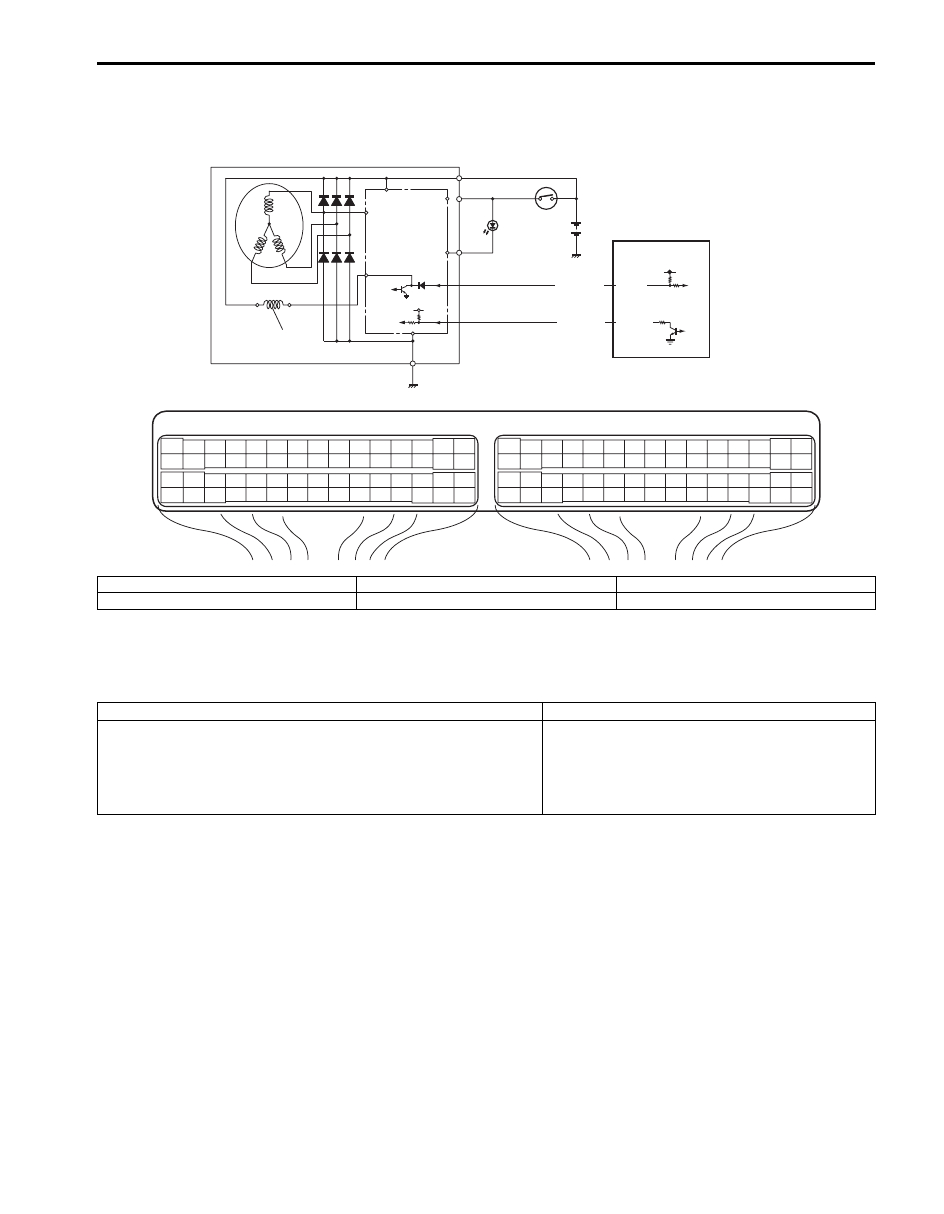
System and Wiring Diagram
Generator Control System Description
Refer to “Generator Control System Description”.
DTC Detecting Condition and Trouble Area
DTC Confirmation Procedure
1) With ignition switch turned OFF, connect scan tool to DLC
2) Turn ON ignition switch and clear DTC.
3) Make sure that all accessory switches are tuned OFF.
4) Start engine and warm it up to normal operating temperature (ECT approx. 90 – 95
°C, 193 – 203 °F).
5) Turn ON the following accessory switches.
• Head light switch.
• Blower motor switch (max position).
• Rear defogger switch.
6) Increase engine speed to 4000 rpm and keep it for 10 sec or more.
7) Decrease engine speed to idle.
8) Check DTC and pending DTC.
IG
L
C
FR
E
4
2
BRN/BLK
C37-8
BRN/BLK
C37-28
B
E23
C37
3
4
18
19
5
6
7
10
11
17
20
47
46
49
50
51
21
22
52
16
25
9
24
14
29
55
57
54 53
59
60
58
2
26
27
28
15
30
56
48
32
31
34
35
36
37
40
42
39 38
44
45
43
41
33
1
12
13
23
8
3
4
18
19
5
6
7
10
11
17
20
47
46
49
50
51
21
22
52
16
25
9
24
14
29
55
57
54 53
59
60
58
2
26
27
28
15
30
56
48
32
31
34
35
36
37
40
42
39 38
44
45
43
41
33
1
12
13
23
8
1
3
5
I5JB0A110063-01
1. Generator
3. Field coil
5. Ignition switch
2. IC regulator
4. ECM
6. Charge lamp
DTC detecting condition
Trouble area
• Battery voltage is higher than specification even through
generator control is maximum regulation (duty 100%).
• Battery voltage is lower than specification even through
generator control is minimum regulation (duty 0%) and electric
load is less than 20 A.
Generator and/or its circuit
Electric load current sensor (for J20 engine)
ECM

1A-163 Engine General Information and Diagnosis:
DTC Troubleshooting
NOTE
Before this trouble shooting is performed, read the precautions for DTC troubleshooting referring to
“Precautions For DTC Troubleshooting”.
Step
Action
Yes
No
1
Was “Engine and Emission Control System Check”
performed?
Go to Step 2.
Go to “Engine and
Emission Control
System Check”.
2
Generator control circuit check
1) Disconnect connector from generator and ECM with
ignition switch turned OFF.
2) Check for proper connection of wire terminal to
generator connector and to ECM connector.
3) If connections are OK, check generator control circuit for
the following.
• Resistance of generator control circuit wire between
generator connector and ECM connector is less than
1
Ω (continuity check)
• Resistance between generator control circuit wire of
generator connector and vehicle body ground is
infinity (ground circuit short check)
• Voltage between generator control circuit wire of
generator connector and vehicle body ground is 0 V
with ignition switch tuned ON (power circuit short
check)
Are they in good condition?
Go to Step 3.
Repair or replace
defective wire.
3
Generator check
1) Check for generator output referring to “Generator Test
(Undercharged Battery Check) in Section 1J”.
Is check result satisfactory?
For J20 engine, go to
Step 4.
For M16 engine,
Substitute a known
good ECM and recheck.
Repair or replace
generator.
4
Electric load current sensor check (for J20 engine)
1) Check for electric load current sensor output referring to
“Electric Load Current Sensor On-Vehicle Inspection
(For J20 Engine) in Section 1C”.
Is check result satisfactory?
Substitute a known
good ECM and recheck.
Replace electric load
current sensor.

Engine General Information and Diagnosis: 1A-164
DTC P0625 / P0626: Generator Field Terminal Circuit Low / High
S5JB0A1104091
System and Wiring Diagram
Refer to “DTC P0620: Generator Control Circuit”.
Generator Control System Description
Refer to “Generator Control System Description”.
DTC Detecting Condition and Trouble Area
DTC Confirmation Procedure
1) With ignition switch turned OFF, connect scan tool to DLC.
2) Turn ON ignition switch and clear DTC.
3) Make sure that all accessory switch is tuned OFF.
4) Start engine and warm it up to normal operating temperature (ECT approx. 90 – 95
°C, 193 – 203 °F).
5) Turn ON following accessory switch.
• Head lights switch.
• Blower motor switch (max position).
• Rear defogger switch.
6) Increase engine speed to 4000 rpm and keep it for 10 sec. or more.
7) Decrease engine speed to idle.
8) Check DTC and pending DTC.
DTC detecting condition
Trouble area
P0625:
Generator field coil duty is 100% (low voltage) for more than
specified time even through generator control is maximum
regulation (control duty 100%) or Generator field coil duty is 100%
(low voltage) when engine is starting.
P0626:
Generator field coil duty is 0% (high voltage) for more than
specified time even through generator control is minimum
regulation (control duty 0%).
Generator and/or its circuit
ECM
Нет комментариевНе стесняйтесь поделиться с нами вашим ценным мнением.
Текст