Suzuki Grand Vitara JB416 / JB420. Manual — part 407
10A-3 Cruise Control System:
Cancel Conditions of Cruise Control System
S5JB0AA101003
Constant cruising is cancelled under the following
conditions.
• *Ignition switch is turned OFF.
• MAIN switch is turned OFF.
• Vehicle speed becomes lower than minimum
operating speed (40 km/h (25 mile/h)).
• *Vehicle speed varies beyond cancel speed range (–
10 km/h (–6 mile/h)) from preset speed.
• *Brake pedal is depressed. (Brake light switch is
turned ON).
• *Clutch pedal is depressed (Clutch pedal position
switch is turned ON) (For M/T vehicle).
• *Selector lever is shifted to “P”, “R” or “N” range.
• *CANCEL switch is turned ON.
NOTE
When constant cruising is cancelled under
any condition with * (asterisk), vehicle speed
before cancellation can be resumed by
operating RES/ACC switch, provided that
vehicle speed is higher than 40 km/h (25 mile/
h).
Schematic and Routing Diagram
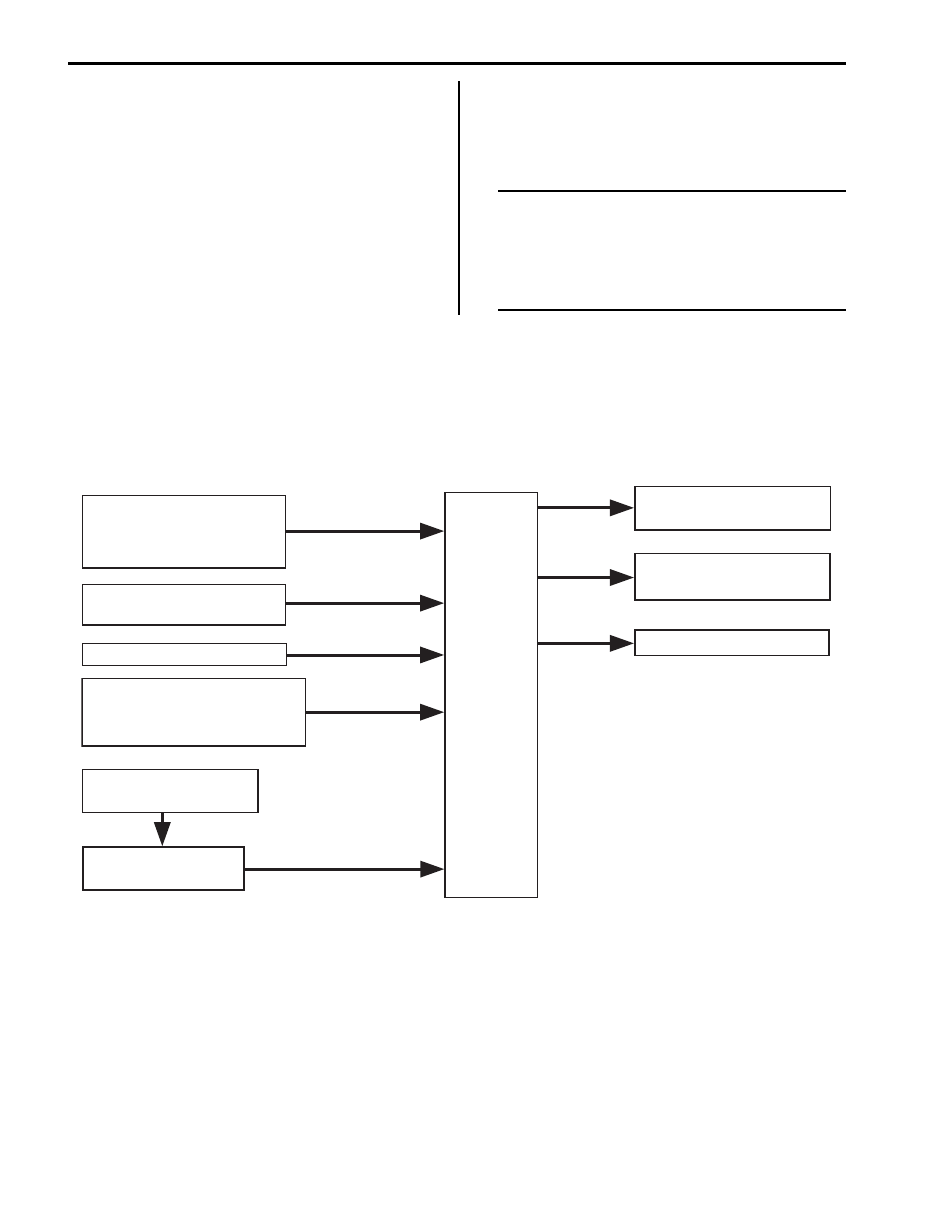
Cruise Control System Input / Output Diagram
S5JB0AA102002
Input
Output
MAIN switch
Cruise control switch
RES/ACC switch
SET/COAST switch
CANCEL switch
CPP switch
(M/T model)
Stop (brake) lamp switch
Wheel speed sensor
ABS hydraulic unit /
(vehicle speed signal)
ECM
Electric throttle body
(throttle valve control)
Combination meter
(Indicator lamp control)
TCM (Shift control)
control module
(A/T model)
Transmission range switch
( or range signal)
“P”, “R”
“N”
I5JB0AA10002-04
Cruise Control System: 10A-4
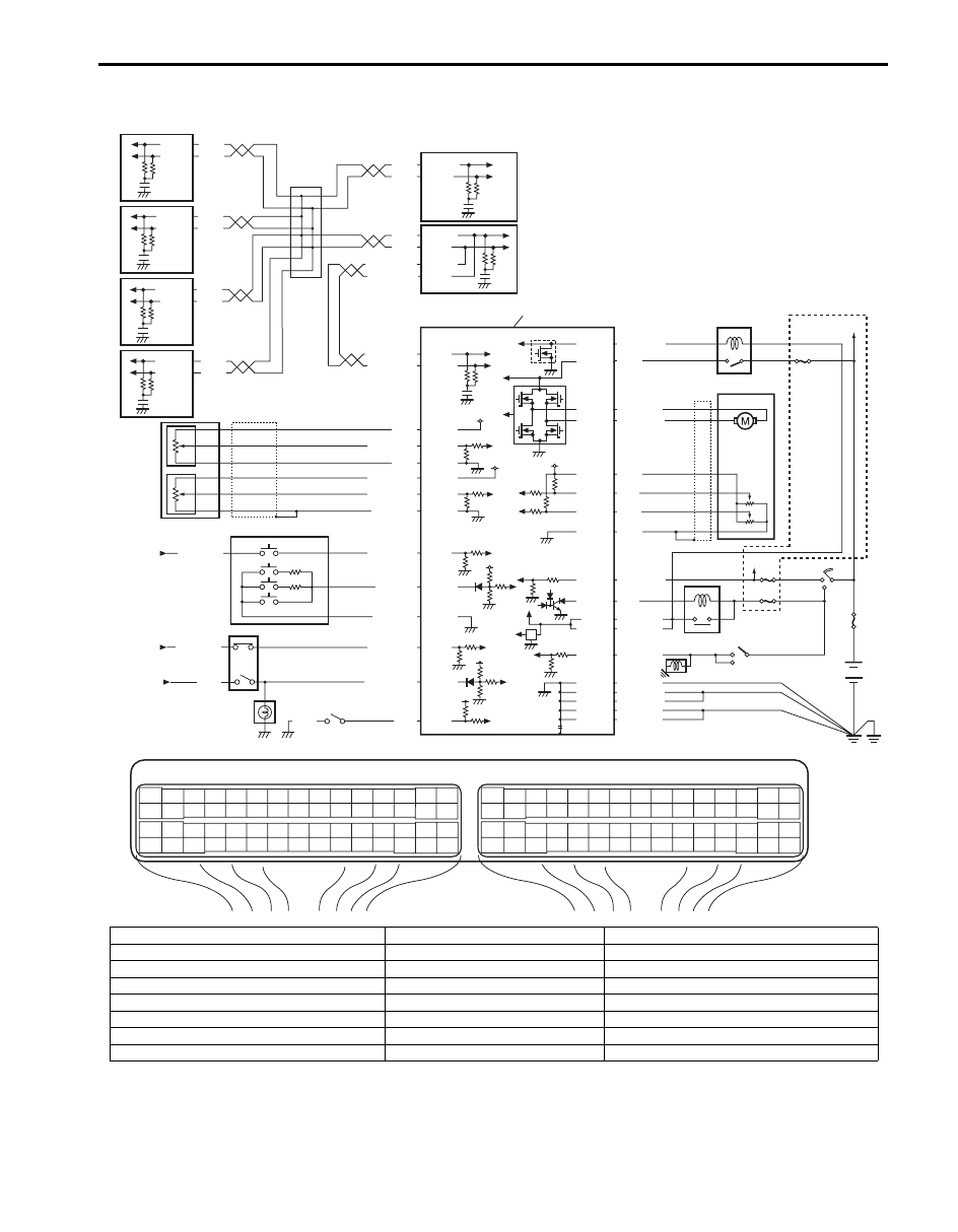
Cruise Control System Wiring Diagram
S5JB0AA102001
IG1
+BB
+BB
IG1
RED
G44-19
WHT
RED
E03-12
E03-6
WHT/BLU
WHT/RED
WHT/BLU
WHT/RED
E23-4
E23-19
E23-56
5V
5V
5V
5V
12V
12V
E03-8
E03-10
WHT
RED
E92-17
E92-7
WHT
RED
E91-22
E91-23
WHT
RED
G31-1
G31-3
WHT
WHT
ORN
RED
G28-8
G28-10
IG1
E23-6
E23-8
E23-7
E23-22
E23-21
E23-20
C37-58
C37-15
C37-29
C37-41
C37-40
C37-54
C37-53
C37-44
C37-45
C37-22
E23-16
E23-60
E23-29
E23-1
C37-48
WHT
G44-18
E23-55
E23-54
E23-53
E23-52
E23-51
WHT/BLU
BLK/WHT
LT GRN
BLK/YEL
YEL/GRN
BLU/BLK
BLU/BLK
BLU
BLK
GRN/WHT
GRN
BLK/YEL
BLK/YEL
BLK/YEL
BLU/BLK
BLK/WHT
BLU/RED
BLU/YEL
BLU/ORN
GRN
GRN
RED
BLK
WHT
BLU
BLU/BLK
BLK/ORN
BLK/ORN
BLK/YEL
BLU/GRN
BLU/YEL
ORN/BLU
C37-30
E23-50
E23-17
E23
C37
3
4
18
19
5
6
7
10
11
17
20
47
46
49
50
51
21
22
52
16
25
9
24
14
29
55
57
54 53
59
60
58
2
26
27
28
15
30
56
48
32
31
34
35
36
37
40
42
39 38
44
45
43
41
33
1
12
13
23
8
3
4
18
19
5
6
7
10
11
17
20
47
46
49
50
51
21
22
52
16
25
9
24
14
29
55
57
54 53
59
60
58
2
26
27
28
15
30
56
48
32
31
34
35
36
37
40
42
39 38
44
45
43
41
33
1
12
13
23
8
[A]
20
21
22
23
2
19
18
1
3
4
5
6
7
8
10
9
15
13
14
16
12
11
17
I5JB0AA10003-05
[A]: ECM connector (viewed from harness side)
8. Stop (brake) lamp switch
16. Ignition switch
1. ECM
9. CPP switch
17. Junction block assembly
2. Accelerator pedal position sensor
10. Brake lamp
18. ABS hydraulic unit / control module
3. Cruise control switch assembly
11. Electric throttle valve relay
19. Combination meter
4. MAIN switch
12. Electric throttle body assembly
20. BCM
5. RES/ACC switch
13. Main relay
21. 4WD control module (if equipped)
6. SET/COAST switch
14. Transmission range switch
22. TCM (if equipped)
7. CANCEL switch
15. Starting motor
23. Keyless start control module (if equipped)
10A-5 Cruise Control System:
Diagnostic Information and Procedures
Cruise Control System Symptom Diagnosis
S5JB0AA104001
NOTE
• ECM uses TCM, ABS hydraulic unit/control module and CAN communication to transmit and receive
data for cruise control. Therefore, check that no DTC is detected from ECM, TCM or ABS hydraulic
unit / control module before performing this Cruise Control System Symptom Diagnosis. If DTC is
detected, correct trouble indicated by that DTC first.
• Check each part in the order from the top of the following list.
Condition
Possible cause
Correction / Reference Item
CRUISE or SET indicator
lamp does not turn ON or
OFF
MAIN switch faulty
Check MAIN switch for function referring to
“Cruise Control Switch Inspection”.
SET/COAST switch faulty
Check SET/COAST switch for function
referring to “Cruise Control Switch Inspection”.
Wiring or grounding faulty
Repair.
Combination meter faulty
Replace.
ECM faulty
Replace after making sure that none of above
parts is faulty.
Vehicle speed can not be
set
MAIN switch faulty
Check MAIN switch for function referring to
“Cruise Control Switch Inspection”.
SET/COAST switch faulty
Check SET/COAST switch for function
referring to “Cruise Control Switch Inspection”.
Brake (stop) Lamp switch faulty
Check brake (stop) lamp switch for function
referring to “Stop (Brake) Lamp Switch
Inspection”.
CPP switch faulty (M/T model)
Check CPP switch for function referring to
“Clutch Pedal Position (CPP) Switch (for
Cruise Control) Inspection and Adjustment”.
Wiring or grounding faulty
Repair.
ECM faulty
Replace after making sure that none of above
parts is faulty.
Acceleration or
deceleration is not
available by using RES/
ACC or SET/COAST
switch
RES/ACC or SET/COAST switch faulty Check RES/ACC or SET/COAST switch for
function referring to “Cruise Control Switch
Inspection”.
Wiring or grounding faulty
Repair.
ECM faulty
Replace after making sure that none of above
parts is faulty.
Cruise control cannot be
cancelled
CANCEL switch faulty
Check CANCEL switch for function referring to
“Cruise Control Switch Inspection”.
Stop (brake) lamp switch faulty
Check brake (stop) lamp switch for function
referring to “Stop (Brake) Lamp Switch
Inspection”.
CPP switch faulty
Check CPP switch for function referring to
“Clutch Pedal Position (CPP) Switch (for
Cruise Control) Inspection and Adjustment”.
Wiring or grounding faulty
Repair.
ECM faulty
Replace after making sure that none of above
parts is faulty.
Cruise control at vehicle
speed stored in memory
cannot be resumed after
cruise control was
cancelled by means other
than MAIN switch
RES/ACC switch faulty
Check RES/ACC switch for function referring
to “Cruise Control Switch Inspection”.
Wiring or grounding faulty
Repair.
ECM faulty
Replace after making sure that none of above
parts is faulty.
Cruise Control System: 10A-6
Inspection of Cruise Control System Circuit
S5JB0AA104012
Cruise control system is controlled by ECM. Each switch and circuit can be checked by taking measurement of
terminal voltage and terminal to terminal resistance of ECM. When measuring these values, be sure to read
precautions for measurement described under “Inspection of ECM and Its Circuits in Section 1A”.
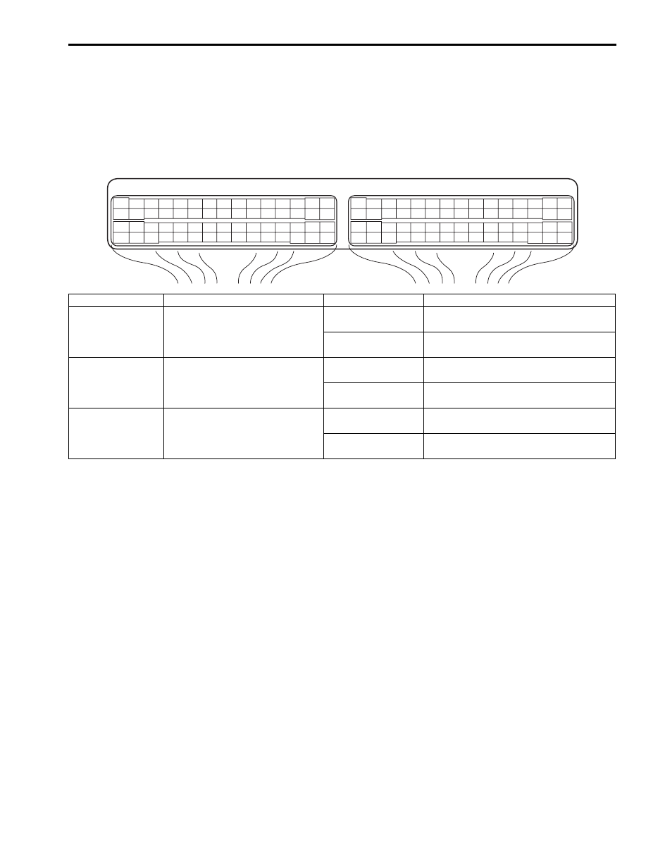
Voltage Check
Check voltage between the following terminals with ECM connector connected.
Terminal arrangement of ECM connector viewed from harness side
E23
C37
3
4
18
19
5
6
7
10
11
17
20
47
46
49
50
51
21
22
52
16
25
9
24
14
29
55
57
54 53
59
60
58
2
26
27
28
15
30
56
48
32
31
34
35
36
37
40
42
39 38
44
45
43
41
33
1
12
13
23
8
3
4
18
19
5
6
7
10
11
17
20
47
46
49
50
51
21
22
52
16
25
9
24
14
29
55
57
54 53
59
60
58
2
26
27
28
15
30
56
48
32
31
34
35
36
37
40
42
39 38
44
45
43
41
33
1
12
13
23
8
I5JB0AA10004-01
Terminals
Circuit
Normal Voltage
Condition
E23-7 – ground
CPP switch circuit
10 – 14 V
Ignition switch is at ON position and
clutch pedal is not depressed.
0 V
Ignition switch is at ON position and
clutch pedal is depressed.
E23-8 – ground
Stop (Brake) lamp switch circuit
10 – 14 V
Ignition switch is at ON position and
brake pedal is not depressed.
0 V
Ignition switch is at ON position and
brake pedal is depressed.
E23-20 – ground Stop (Brake) lamp switch circuit
0 V
Ignition switch is at ON position and
brake pedal is not depressed.
10 – 14 V
Ignition switch is at ON position and
brake pedal is depressed.
Нет комментариевНе стесняйтесь поделиться с нами вашим ценным мнением.
Текст