Suzuki Grand Vitara JB416 / JB420. Manual — part 406
10-ii Table of Contents
General Description . . . . . . . . . . ...10C-2
Immobilizer Control System Introduction . . ..10C-2
On-Board Diagnostic System Description
(Self-diagnosis Function) . . . . . . . . 10C-2
Schematic and Routing Diagram. . . . . ..10C-3
Immobilizer Control System Wiring Circuit
Diagram . . . . . . . . . . . . . . ..10C-3
Component Location . . . . . . . . . . .10C-4
Immobilizer Control System Components
Location . . . . . . . . . . . . . . ..10C-4
Diagnostic Information and Procedures. . ..10C-5
Immobilizer Control System Check . . . . ...10C-5
Diagnostic Trouble Code (DTC) Check. . . .10C-6
Diagnostic Trouble Code (DTC) Clearance . ..10C-6
Diagnostic Trouble Code (DTC) Table. . . ..10C-6
Scan Tool Data . . . . . . . . . . . . .10C-7
Immobilizer Indicator Lamp Does Not Come
ON with Ignition Switch ON and Engine Stop ..10C-8
Immobilizer Indicator Lamp Remains ON after
Engine Start . . . . . . . . . . . . . 10C-9
DTC P1614: Transponder Response Error. ...10C-9
DTC P1615: Steering Lock Unit
Communication Error (for Vehicle with
Keyless Start System). . . . . . . . ...10C-10
DTC P1616: Unregistered Keyless Start
Control Module (for Vehicle with Keyless
Start System) . . . . . . . . . . . . 10C-13
DTC P1618: Keyless Start Control Module
CAN Communication Error (for Vehicle with
Keyless Start System). . . . . . . . ...10C-13
DTC P1621: Immobilizer Communication
Line Error . . . . . . . . . . . . . ..10C-15
DTC P1622: EEPROM Error. . . . . . ...10C-18
DTC P1623: Unregistered Transponder . . .10C-18
DTC P1625: Immobilizer Antenna Error. . ..10C-19
DTC P1636: Immobilizer Information
Registration Failure . . . . . . . . . ...10C-20
DTC P1638: Immobilizer Information
Mismatched. . . . . . . . . . . . ...10C-21
Inspection of Immobilizer Control Module
(ICM) and Its Circuit . . . . . . . . . ..10C-22
Repair Instructions . . . . . . . . . . ..10C-24
Immobilizer Control Module (ICM) Removal
and Installation . . . . . . . . . . . ..10C-24
Registration of the Ignition Key . . . . . ...10C-24
Procedure after ECM Replacement . . . . 10C-24
Special Tools and Equipment . . . . . . .10C-25
Special Tool . . . . . . . . . . . . . 10C-25
Keyless Start System. . . . . . . .10E-1
Precautions. . . . . . . . . . . . . . .10E-1
Precautions in Diagnosing Troubles . . . . .10E-1
General Description . . . . . . . . . . ...10E-2
Keyless Start System Description . . . . . .10E-2
Parts and Functions . . . . . . . . . . ..10E-3
Keyless Engine Start Function . . . . . . ..10E-4
Door Lock Function of Keyless Start System. 10E-5
Operation Area of Remote Controller. . . . 10E-6
Alarm Function . . . . . . . . . . . . ..10E-7
CAN Communication of Keyless Start System ..10E-7
Schematic and Routing Diagram . . . . . ..10E-8
Keyless Start System Electric Wiring Circuit
Diagram. . . . . . . . . . . . . . ...10E-8
Diagnostic Information and Procedures . . ..10E-9
Self-Diagnosis Function . . . . . . . . . 10E-9
Keyless Start System Diagnosis Introduction ...10E-9
Keyless Start System Check. . . . . . . .10E-9
Customer questionnaire (example) . . . . .10E-10
Key Indicator Lamp Check . . . . . . . ..10E-10
DTC Check. . . . . . . . . . . . . ..10E-11
DTC Table. . . . . . . . . . . . . ...10E-12
DTC Clearance . . . . . . . . . . . ...10E-12
Keyless Start System Symptom Diagnosis . .10E-13
Keyless Start System Operation Inspection. 10E-14
Door Lock Operation (Keyless Start System) .10E-14
Inspection of Keyless Start Control Module
and Its Circuits . . . . . . . . . . . ..10E-15
No DTC Detection After Performing DTC
Check . . . . . . . . . . . . . . . 10E-20
Key Indicator Lamp Circuit Check (Key
indicator lamp doesn’t light when ignition
knob switch is pushed.). . . . . . . . .10E-22
Keyless Start Control Module Power and
Ground Circuit Check. . . . . . . . . 10E-23
DTC No. 11: Communication Error with
Steering Lock Unit. . . . . . . . . . .10E-24
DTC No. 13 / No. 14: Release Signal Error
from Steering Lock Unit / Steering Lock Unit
Malfunction. . . . . . . . . . . . . 10E-26
DTC No. 21 / No. 22: Internal Error of Keyless
Start Control Module (EEPROM reading
error) / (EEPROM writing error) . . . . . 10E-26
DTC No. 31: Lost Communication with BCM ..10E-27
DTC No. 33: Control Module Communication
Bus Off . . . . . . . . . . . . . . ..10E-29
DTC No. 51 / No. 52 / No. 53: Driver Side /
Passenger Side / Rear End Door Request
Switch Failure. . . . . . . . . . . . 10E-31
Repair Instructions . . . . . . . . . . ..10E-33
Antennas and Request Switches Removal
and Installation . . . . . . . . . . . ..10E-33
Front Door (Driver and Passenger Side) Rear
End Door Request Switch Inspection. . . 10E-34
Steering Lock Unit Removal and Installation ..10E-34
Steering Lock Unit Inspection . . . . . . .10E-34
Front Door Lock Switch Inspection . . . . .10E-34
Keyless start control module Removal and
Installation . . . . . . . . . . . . . .10E-35
Remote Controller Inspection. . . . . . ..10E-35
Replacement of Remote Controller Battery . 10E-35
Registration Procedure for Remote Controller
Precautions: 10-1
Control Systems
Precautions
Precautions
Precautions for Control Systems
S5JB0AA000001
Air Bag Warning
Refer to “Air Bag Warning in Section 00”.
10A-1 Cruise Control System:
Control Systems
Cruise Control System
General Description
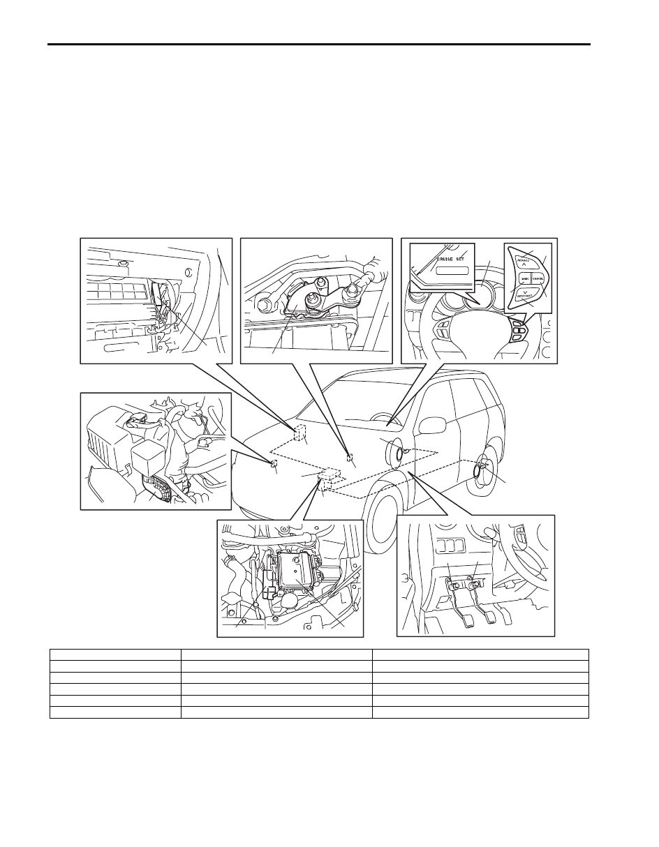
Cruise Control System Construction
S5JB0AA101001
The cruise control system is a device which maintains a preset vehicle speed while driving at a high speed, e.g., on a
highway. It allows the driver to drive his vehicle at a constant speed of 40 km/h (25 mile/h) or higher without
depressing the accelerator pedal. The system also has such functions as to change the vehicle speed without
operating the accelerator pedal (but using SET/COAST and RES/ACC switches), cancel cruise control (CANCEL
switch) and resume the speed in memory automatically after cruise control is cancelled (RES/ACC switch). The
system mainly consists of electric throttle body assembly, ECM, cruise control switch (MAIN switch, SET/COAST
switch, RES/ACC switch and CANCEL switch), etc.
15
14
16
16
10
10
13
15
14
9
11
12
13
3
5
8
6
7
4
1
2
9
I5JB0AA10001-01
1. Combination meter
7. SET/COAST switch
13. ECM
2. “CRUISE” indicator lamp
8. CANCEL switch
14. Transmission range switch (A/T vehicle only)
3. “SET” indicator lamp
9. Wheel speed sensor (vehicle speed signal)
15. TCM (A/T vehicle only)
4. Cruise control switch assembly
10. ABS hydraulic unit / control module
16. Electric throttle body assembly
5. RES/ACC switch
11. Brake light switch with brake pedal position switch
6. MAIN switch
12. Clutch pedal position switch (M/T vehicle only)

Cruise Control System: 10A-2
Components and Functions of Cruise Control System
S5JB0AA101002
Component
Function
ECM and electric throttle body
assembly
ECM executes centralized control over all functions including setting a constant speed,
resuming it, setting coast, cancelling cruise control limiting minimum speed.
ECM controls electric throttle valve opening to keep actual vehicle speed at set (target)
speed.
MAIN switch
This switch has a momentary contact type button to press cruise control
system ON and OFF.
SET/COAST switch
When this switch is pressed (ON) and then released (OFF) while vehicle is running at
a speed 40 km/h (25 mile/h) or higher, vehicle speed at that OFF moment is stored in
memory and it is maintained (constant cruising).
Pressing this switch (ON) continuously during constant cruising keeps slowing down
vehicle speed as long as it is ON. When it is released (OFF), vehicle speed at that
moment is stored in memory and vehicle starts constant cruising.
RES/ACC switch
When this switch is pressed (ON) during constant cruising, vehicle speed keeps
increasing as long as it is ON. When it is released (OFF), vehicle speed at that
moment is stored in memory and vehicle starts constant cruising. If vehicle speed is
higher than 40 km/h (25 mile/h) after cruise control is cancelled, pressing this switch
ON momentarily will resume the speed at which vehicle was running before
cancellation.
CANCEL switch
When this switch is pressed (ON), cruise control (throttle valve control) is cancelled.
Wheel speed sensor (vehicle
speed signal)
ECM receives speed sensor signal from ABS hydraulic unit / control module through
CAN communication and calculates vehicle speed using that signal.
Brake light switch
Brake light switch has 2 contact points. One contact point closes when brake pedal is
depressed to light brake light and provides a voltage signal to the ECM.
The other contact point (brake pedal position switch) opens when brake pedal is
depressed, to shut off power to cruise control of ECM, thereby cancelling cruise
control (throttle valve control).
This switch is installed to cancel cruise control (constant cruising).
Clutch pedal position switch
(M/T vehicle only)
When clutch pedal is depressed, clutch pedal position switch closes and provides a
ground signal to ECM.
ECM cancels cruise control (throttle valve control) when this signal is inputted.
Transmission range switch (A/
T vehicle only)
When selector lever is placed in either “P”, “R” or “N” position, transmission range
switch closes and provides a ground signal to TCM. TCM transmits signal from
transmission range switch to ECM through CAN communication. When ECM receives
a signal indicating that selector lever position is “P”, “R” or “N”, it cancels cruise control
(throttle valve control).
TCM
TCM receives the SET signal for the cruise control from ECM through CAN
communication. When TCM receives the SET signal from ECM, the gear shift control
is performed by using the gear shift map for the cruise control changed from the one
for normal gear shift. For details, refer to “Automatic Gear Shift Table in Section 5A”.
“CRUISE” indicator lamp
In the state with ignition switch ON and cruise control system OFF, pressing MAIN
switch once and releasing it will activate the cruise control system and ECM will cause
indicator lamp to light up.
“SET” indicator lamp
It lights up when cruise control (throttle valve control) is functioning.
Нет комментариевНе стесняйтесь поделиться с нами вашим ценным мнением.
Текст