Suzuki Grand Vitara JB416 / JB420. Manual — part 228
5A-46 Automatic Transmission/Transaxle:
“POWER” Light Circuit Check – Light Does Not Come “ON” at Ignition Switch ON
S5JB0A5104065
Troubleshooting
DTC P0705: Transmission Range Sensor Circuit Malfunction
S5JB0A5104026
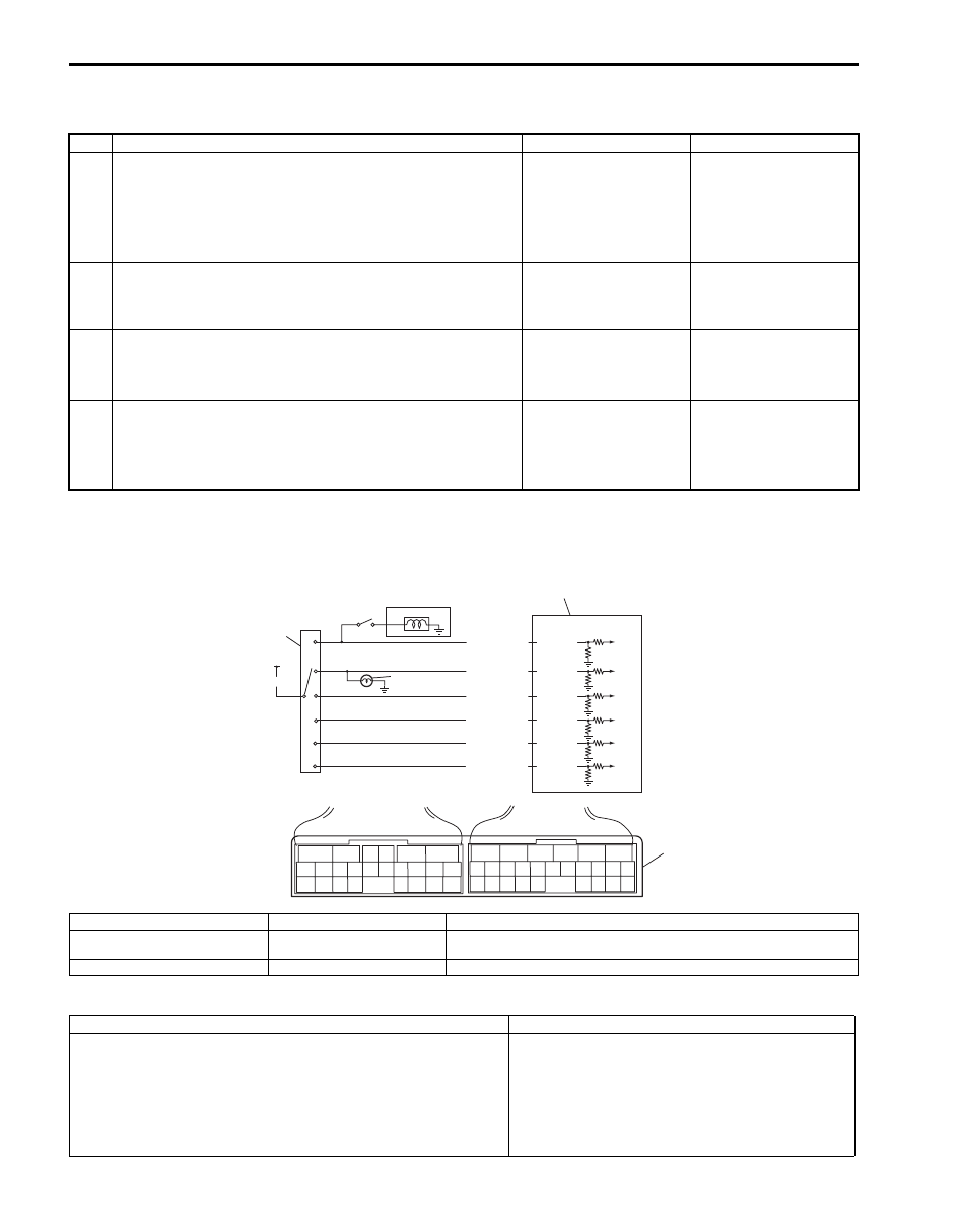
Wiring Diagram
DTC Detecting Condition and Trouble Area
Step
Action
Yes
No
1
Combination Meter Power Supply Check
1) Turn ignition switch ON.
Does other indicator / warning lights in combination meter
comes ON?
Go to Step 2.
Repair combination
meter power supply
circuit referring to
“Combination Meter
Circuit Diagram in
Section 9C”.
2
1) TCM power and ground circuit check referring to “TCM
Power and Ground Circuit Check”.
Is it in good condition?
Go to Step 3.
Repair or replace.
3
DTC check
1) Check DTC referring to “DTC Check”.
Is there DTC P1774 or P1775?
Go to applicable DTC
diag. flow.
Go to Step 4.
4
Combination Meter Function Check
1) Turn ignition switch ON.
Does A/T selector position indicator show correct select
lever position?
Replace combination
meter.
Substitute a known-
good TCM and recheck.
2
6
1
4
P
R
N
D
2
L
5
3
BLK/RED
RED
YEL/GRN
PNK/BLU
PNK/GRN
GRN/ORN
GRN/WHT
E93-20
E93-1
E93-8
E93-7
E93-19
E93-18
6
5
16 15 14 13 12 11
4 3
24 23
21
22
10 9
8
7
2
1
19
20
18 17
E92
17 16
26 25
15 14
6
5
3
4
2
13 12
23 22
24
11 10 9
21 20 19
8 7
18
1
E93
7
I5JB0A510020-01
1. TCM
4. Brake light switch
7. Terminal arrangement of TCM connector (viewed from harness side)
2. Transmission range sensor
(switch)
5. Back-up light
3. From ignition switch
6. Shift lock solenoid
DTC Detecting Condition
Trouble Area
Multiple signals are inputted simultaneously for 2 seconds.
(1 driving cycle detection logic)
• Select cable maladjusted.
• Transmission range sensor (switch)
maladjusted.
• Transmission range sensor (switch) or its circuit
malfunction.
• TCM

Automatic Transmission/Transaxle: 5A-47
DTC Confirmation Procedure
1) Connect scan tool to DLC with ignition switch OFF.
2) Clear DTCs in TCM and ECM memories by using scan tool.
3) Start engine and shift select lever to “D” range.
4) Keep engine running at idle speed for 25 seconds or more.
5) Check DTC, pending DTC and freeze-frame data.
DTC Troubleshooting
Step
Action
Yes
No
1
Was “A/T System Check” performed?
Go to Step 2.
Go to “A/T System
Check”.
2
Do you have SUZUKI scan tool?
Go to Step 3.
Go to Step 4.
3
Check transmission range sensor (switch) circuit for
operation
Check by using SUZUKI scan tool:
1) Connect SUZUKI scan tool to DLC with ignition switch
OFF.
2) Turn ignition switch ON and check transmission range
sensor signal (“P”, “R”, “N”, “D”, “2” or “L”) on display
when shifting select lever to each range.
Is applicable range indicated?
Intermittent trouble.
Check for intermittent
trouble referring to
“Intermittent and Poor
Connection Inspection
in Section 00”.
Go to Step 5.
4
Check transmission range sensor (switch) circuit for
operation
Check without using SUZUKI scan tool:
1) Turn ignition switch ON.
2) Check voltage at terminals “E93-1”, “E93-7”, “E93-8”,
“E93-18”, “E93-19” and “E93-20” respectively with select
lever shifted to each range.
Taking terminal “E93-1” as an example, is battery
voltage will be indicated only when shift lever is shifted to
“R” range and 0 V for other ranges as shown in table.
Check voltage at other terminals likewise, referring to
table.
Are check results satisfactory?
Intermittent trouble.
Check for intermittent
trouble referring to
“Intermittent and Poor
Connection Inspection
in Section 00”.
Go to Step 5.
5
Check transmission range sensor (switch) for
installation position
1) Check transmission range sensor (switch) for installation
position referring to “Transmission Range Sensor
Inspection and Adjustment”.
Is it adjusted correctly?
Go to Step 6.
Adjust transmission
range sensor (switch)
and recheck.
6
Check select cable for adjustment
1) Check select cable for adjustment referring to “Select
Is it adjusted correctly?
Go to Step 7.
Adjust select cable and
recheck.
7
Check transmission range sensor (switch)
1) Check transmission range sensor (switch) referring to
“Transmission Range Sensor Inspection and
Adjustment”.
Are check results satisfactory?
Transmission range
sensor circuit shorted to
power circuit or shorted
each other. If wires and
connections are OK,
substitute a known-
good TCM and recheck.
Replace transmission
range sensor (switch).

5A-48 Automatic Transmission/Transaxle:
DTC P0707: Transmission Range Sensor Circuit Low
S5JB0A5104027
Wiring Diagram
Refer to “DTC P0705: Transmission Range Sensor Circuit Malfunction”.
DTC Detecting Condition and Trouble Area
DTC Confirmation Procedure
1) Connect scan tool to DLC with ignition switch OFF.
2) Clear DTCs in TCM and ECM memories by using scan tool.
3) Start engine and shift select lever to “D” range.
4) Start vehicle and increase vehicle speed to 50 km/h (31 mile/h) or more for 2 minutes.
5) Stop vehicle and turn ignition switch OFF.
6) Repeat Step 3) to 5) one time.
7) Stop vehicle.
8) Check DTC, pending DTC and freeze-frame data.
DTC Troubleshooting
Terminal
E93-20
E93-1
E93-8
E93-7
E93-19
E93-18
Select lever
position
P
8 – 14 V
0 V
0 V
0 V
0 V
0 V
R
0 V
8 – 14 V
0 V
0 V
0 V
0 V
N
0 V
0 V
8 – 14 V
0 V
0 V
0 V
D or 3
0 V
0 V
0 V
8 – 14 V
0 V
0 V
2
0 V
0 V
0 V
0 V
8 – 14 V
0 V
L
0 V
0 V
0 V
0 V
0 V
8 – 14 V
DTC Detecting Condition
Trouble Area
Transmission range switch signal (P, R, N, D, 2, L) is not inputted
for more than 2 seconds in the following condition.
• Vehicle speed is more than 30 km/h (19 mile/h).
And
• Engine speed is more than 1500 rpm.
(2 driving cycle detection logic)
• Select cable maladjusted.
• Transmission range sensor (switch)
maladjusted.
• Transmission range sensor (switch) or its circuit
malfunction.
• TCM
Step
Action
Yes
No
1
Was “A/T System Check” performed?
Go to Step 2.
Go to “A/T System
Check”.
2
Do you have SUZUKI scan tool?
Go to Step 3.
Go to Step 4.
3
Check transmission range sensor (switch) circuit for
operation
Check by using SUZUKI scan tool:
1) Connect SUZUKI scan tool to DLC with ignition switch
OFF.
2) Turn ignition switch ON and check transmission range
sensor signal (“P”, “R”, “N”, “D”, “2” or “L”) on display
when shifting select lever to each range.
Is applicable range indicated?
Intermittent trouble.
Check for intermittent
trouble referring to
“Intermittent and Poor
Connection Inspection
in Section 00”.
Go to Step 5.

Automatic Transmission/Transaxle: 5A-49
4
Check transmission range sensor (switch) circuit for
operation
Check without using SUZUKI scan tool:
1) Turn ignition switch ON.
2) Check voltage at terminals “E93-1”, “E93-7”, “E93-8”,
“E93-18”, “E93-19” and “E93-20” respectively with select
lever shifted to each range.
Taking terminal “E93-1” as an example, is battery
voltage will be indicated only when shift lever is shifted to
“R” range and 0 V for other ranges as shown in table.
Check voltage at other terminals likewise, referring to
table.
Are check results satisfactory?
Intermittent trouble.
Check for intermittent
trouble referring to
“Intermittent and Poor
Connection Inspection
in Section 00”.
Go to Step 5.
5
Check transmission range sensor (switch) for
installation position
1) Check transmission range sensor (switch) for installation
position referring to “Transmission Range Sensor
Inspection and Adjustment”.
Is it adjusted correctly?
Go to Step 6.
Adjust transmission
range sensor (switch)
and recheck.
6
Check select cable for adjustment
1) Check select cable for adjustment referring to “Select
Is it adjusted correctly?
Go to Step 7.
Adjust select cable and
recheck.
7
Check transmission range sensor (switch)
1) Check transmission range sensor (switch) referring to
“Transmission Range Sensor Inspection and
Adjustment”.
Are check results satisfactory?
Transmission range
sensor circuit open or
shorted to ground. If
wires and connections
are OK, substitute a
known-good TCM and
recheck.
Replace transmission
range sensor (switch).
Step
Action
Yes
No
Terminal
E93-20
E93-1
E93-8
E93-7
E93-19
E93-18
Select lever
position
P
8 – 14 V
0 V
0 V
0 V
0 V
0 V
R
0 V
8 – 14 V
0 V
0 V
0 V
0 V
N
0 V
0 V
8 – 14 V
0 V
0 V
0 V
D or 3
0 V
0 V
0 V
8 – 14 V
0 V
0 V
2
0 V
0 V
0 V
0 V
8 – 14 V
0 V
L
0 V
0 V
0 V
0 V
0 V
8 – 14 V
Нет комментариевНе стесняйтесь поделиться с нами вашим ценным мнением.
Текст