Suzuki Grand Vitara JB416 / JB420. Manual — part 229
5A-50 Automatic Transmission/Transaxle:
DTC P0712: Transmission Fluid Temperature Sensor “A” Circuit Low
S5JB0A5104029
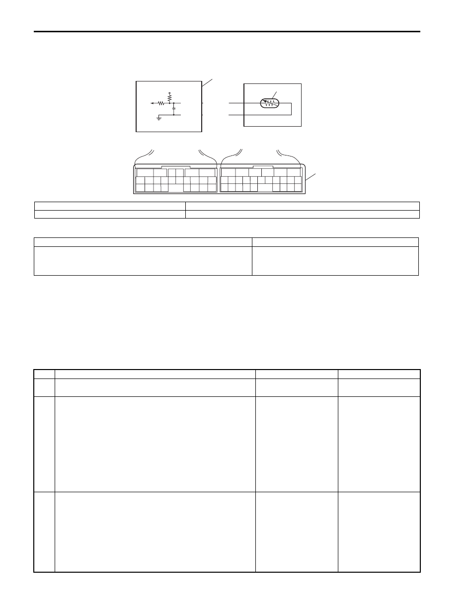
Wiring Diagram
DTC Detecting Condition and Trouble Area
DTC Confirmation Procedure
1) Connect scan tool to DLC with ignition switch OFF.
2) Clear DTCs in TCM and ECM memories by using scan tool.
3) Start engine.
4) Keep engine running at idle speed for 1 minute or more.
5) Check DTC, pending DTC and freeze-frame data.
DTC Troubleshooting
5V
E92-11
E92-12
YEL/BLK
ORN
2
1
3
6
5
16 15 14 13 12 11
4 3
24 23
21
22
10 9
8
7
2
1
19
20
18 17
E92
17 16
26 25
15 14
6
5
3
4
2
13 12
23 22
24
11 10 9
21 20 19
8 7
18
1
E93
I5JB0A510021-02
1. Transmission fluid temperature sensor
3. Terminal arrangement of TCM connector (viewed from harness side)
2. TCM
DTC Detecting Condition
Trouble Area
Transmission temperature sensor terminal voltage is less than
0.05 V for 10 seconds or more after ignition switch ON.
(1 driving cycle detection logic)
• Transmission fluid temperature sensor or its
circuit.
• TCM
Step
Action
Yes
No
1
Was “A/T System Check” performed?
Go to Step 2.
Go to “A/T System
Check”.
2
Check transmission fluid temperature sensor A circuit
for ground short
1) Turn ignition switch OFF.
2) Disconnect TCM connectors from TCM.
3) Check for proper connection to transmission fluid
temperature sensor at terminal “E92-11” and “E92-12”.
4) If OK, check continuity between terminal “E92-11” of
disconnected harness side TCM connector and ground.
Is continuity indicated?
Transmission fluid
temperature sensor
circuit is shorted to
ground. If circuit is OK,
go to Step 3.
Go to Step 3.
3
Inspection transmission fluid temperature sensor
1) Inspection transmission fluid temperature sensor
referring to “Transmission Fluid Temperature Sensor
Inspection”.
Is result satisfactory?
Intermittent trouble or
faulty TCM. Check for
intermittent trouble
referring to “Intermittent
and Poor Connection
Inspection in Section
00”. If OK, substitute a
known-good TCM and
recheck.
Replace valve body
harness including
transmission fluid
temperature sensor
referring to
“Transmission Fluid
Temperature Sensor
Removal and
Installation”.

Automatic Transmission/Transaxle: 5A-51
DTC P0713: Transmission Fluid Temperature Sensor “A” Circuit High
S5JB0A5104030
Wiring Diagram
Refer to “DTC P0712: Transmission Fluid Temperature Sensor “A” Circuit Low”.
DTC Detecting Condition and Trouble Area
DTC Confirmation Procedure
1) Connect scan tool to DLC with ignition switch OFF.
2) Clear DTCs in TCM and ECM memories by using scan tool.
3) Start engine.
4) Start vehicle and increase vehicle speed to about 40 km/h (25 mile/h) for 20 minutes or more.
5) Stop vehicle.
6) Check DTC, pending DTC and freeze-frame data.
DTC Troubleshooting
DTC Detecting Condition
Trouble Area
Transmission temperature sensor terminal voltage is less than
4.89 V under vehicle condition shown in the following.
• Ignition switch is turned on for 15 minutes or more
• Engine coolant temperature is more than 50
°C (122 °F)
(1 driving cycle detection logic)
• Transmission fluid temperature sensor or its
circuit.
• TCM
Step
Action
Yes
No
1
Was “A/T System Check” performed?
Go to Step 2.
Go to “A/T System
Check”.
2
Check transmission fluid temperature sensor circuit for
open
1) Turn ignition switch OFF.
2) Disconnect TCM connectors from TCM.
3) Check for proper connection to transmission fluid
temperature sensor at terminal “E92-11” and “E92-12”.
4) If OK, check continuity between terminal “E92-11” and
“E92-12” of disconnected harness side TCM connector.
Is continuity indicated?
Go to Step 3.
Transmission fluid
temperature sensor
circuit is open circuit.
3
Check transmission fluid temperature sensor circuit for
power supply short
1) Cool down A/T fluid temperature under ambient
temperature.
2) Connect TCM connectors to TCM with ignition switch
OFF.
3) Turn ignition switch ON.
4) Measure voltage between terminal “E92-11” of TCM
connector and ground.
Is it 4.89 V or more?
Transmission fluid
temperature sensor
circuit is shorted to
power supply circuit. If
circuit is OK, go to Step
4.
Intermittent trouble or
faulty TCM. Check for
intermittent trouble
referring to “Intermittent
and Poor Connection
Inspection in Section
00”. If OK, substitute a
known-good TCM and
recheck.
4
Inspection transmission fluid temperature sensor
1) Inspection transmission fluid temperature sensor
referring to “Transmission Fluid Temperature Sensor
Inspection”.
Is result satisfactory?
Intermittent trouble or
faulty TCM. Check for
intermittent trouble
referring to “Intermittent
and Poor Connection
Inspection in Section
00”. If OK, substitute a
known-good TCM and
recheck.
Replace valve body
harness including
transmission fluid
temperature sensor
referring to
“Transmission Fluid
Temperature Sensor
Removal and
Installation”.
5A-52 Automatic Transmission/Transaxle:
DTC P0717: Input / Turbine Speed Sensor Circuit No Signal
S5JB0A5104031
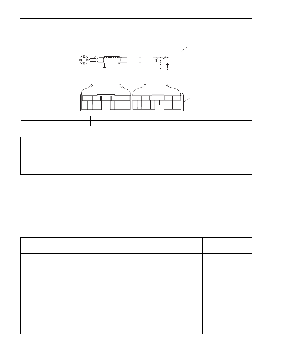
Wiring Diagram
DTC Detecting Condition and Trouble Area
DTC Confirmation Procedure
1) Connect scan tool to DLC with ignition switch OFF.
2) Clear DTCs in TCM and ECM memories by using scan tool.
3) Start engine and shift select lever to “D” range.
4) Start vehicle and increase vehicle speed to about 40 km/h (25 mile/h) for 3 minutes or more.
5) Stop vehicle.
6) Check DTC, pending DTC and freeze-frame data.
DTC Troubleshooting
BLU
PNK
1
2
2.5V
E93-6
E93-16
6
5
16 15 14 13 12 11
4 3
24 23
21
22
10 9
8
7
2
1
19
20
18 17
E92
17 16
26 25
15 14
6
5
3
4
2
13 12
23 22
24
11 10 9
21 20 19
8 7
18
1
E93
3
I5JB0A510022-01
1. TCM
3. Terminal arrangement of TCM connector (viewed from harness side)
2. Input shaft speed sensor
DTC Detecting Condition
Trouble Area
No pulse signal of input shaft speed sensor is inputted for 5
pulses period of output shaft speed sensor through it is
detected more than 600 rpm.
(1 driving cycle detection logic)
• Input shaft speed sensor or its circuit malfunction.
• Improper input shaft speed sensor installation.
• Damaged clutch drum.
• Foreign material attachment to sensor or drum.
• TCM
Step
Action
Yes
No
1
Was “A/T System Check” performed?
Go to Step 2.
Go to “A/T System
Check”.
2
Check input shaft speed sensor circuit
1) Disconnect TCM connectors with ignition switch OFF.
2) Check for proper connection to input shaft speed sensor
at “E93-6” and “E93-16” terminals.
3) If OK, check resistance of sensor circuit.
Resistance of input shaft speed sensor circuit
Between terminals “E93-6” and “E93-16” of
disconnected harness side TCM connector: 560 –
680
Ω at 20 °C (68 °F)
Between terminals “E93-16” of disconnected
harness side TCM connector and ground: No
continuity
Are check results satisfactory?
Go to Step 4.
Go to Step 3.

Automatic Transmission/Transaxle: 5A-53
DTC P0722: Output Speed Sensor Circuit No Signal
S5JB0A5104032
Wiring Diagram
DTC Detecting Condition and Trouble Area
DTC Confirmation Procedure
1) Connect scan tool to DLC with ignition switch OFF.
2) Clear DTCs in TCM and ECM memories by using scan tool.
3) Start engine and shift select lever to “D” range.
4) Start vehicle and increase vehicle speed to about 40 km/h (25 mile/h) for 3 minutes or more.
5) Stop vehicle.
6) Check DTC, pending DTC and freeze-frame data.
3
Inspection input shaft speed sensor
Inspect input shaft speed sensor referring to “Input Shaft
Speed Sensor Inspection”.
Is check result satisfactory?
Input shaft speed
sensor circuit is
malfunction.
Go to Step 4.
4
Check visually input shaft speed sensor and clutch
drum using mirror for following
• No damage
• No foreign material attached
• Correct installation
Are they in good condition?
Intermittent trouble.
Check for intermittent
trouble referring to
“Intermittent and Poor
Connection Inspection
in Section 00”.
Clean, repair or replace.
Step
Action
Yes
No
I2RH01510023-01
2.5V
ORN
WHT
2
1
E93-5
E93-14
6
5
16 15 14 13 12 11
4 3
24 23
21
22
10 9
8
7
2
1
19
20
18 17
E92
17 16
26 25
15 14
6
5
3
4
2
13 12
23 22
24
11 10 9
21 20 19
8 7
18
1
E93
3
I5JB0A510023-01
1. TCM
3. Terminal arrangement of TCM connector (viewed from harness side)
2. Output shaft speed sensor
DTC Detecting Condition
Trouble Area
No pulse signal of output shaft speed sensor is inputted for
23 pulses period of input shaft speed sensor.
(1 driving cycle detection logic)
• Output shaft speed sensor or its circuit malfunction.
• Improper output shaft speed sensor installation.
• Damaged sensor rotor.
• Foreign material attachment to sensor or rotor.
• TCM
Нет комментариевНе стесняйтесь поделиться с нами вашим ценным мнением.
Текст