Suzuki Grand Vitara JB416 / JB420. Manual — part 227
5A-42 Automatic Transmission/Transaxle:
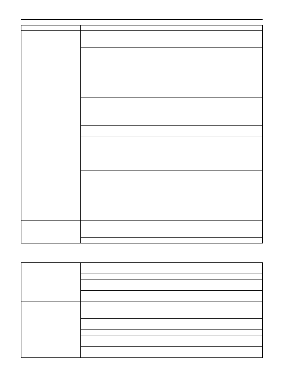
Trouble Diagnosis 3
Off-vehicle repair
Incorrect shift point
Engine abnormal condition
Inspect and repair engine
Malfunction of output shaft speed
sensor
Inspect. If NG, replace.
Malfunction of accelerator pedal position
sensor
Inspect referring to “DTC P0122: Throttle
Position Sensor (Main) Circuit Low in Section
1A”, “DTC P0123: Throttle Position Sensor
(Main) Circuit High in Section 1A”, “DTC
P0222: Throttle Position Sensor (Sub) Circuit
Low in Section 1A” and “DTC P0223: Throttle
Position Sensor (Sub) Circuit High in Section
1A”.
Non operate TCC / lock-up
system
Malfunction of lock-up solenoid valve
Inspect. If NG, replace.
Malfunction of shaft solenoid valve No.1
and/or No.2
Inspect. If NG, replace.
Malfunction of output shaft speed
sensor
Inspect. If NG, replace.
Malfunction of input shaft speed sensor Inspect. If NG, replace.
Malfunction of transmission range
sensor
Inspect. If NG, replace.
Malfunction of transmission fluid
temperature sensor
Inspect. If NG, replace.
Malfunction of pressure control solenoid
valve
Inspect. If NG, replace valve body assembly.
Malfunction of brake light switch
Inspect referring to “Stop (Brake) Lamp Switch
Inspection in Section 9B”. If NG, replace.
Malfunction of accelerator pedal position
sensor
Inspect referring to “DTC P0122: Throttle
Position Sensor (Main) Circuit Low in Section
1A”, “DTC P0123: Throttle Position Sensor
(Main) Circuit High in Section 1A”, “DTC
P0222: Throttle Position Sensor (Sub) Circuit
Low in Section 1A” and “DTC P0223: Throttle
Position Sensor (Sub) Circuit High in Section
1A”.
Faulty valve body component
Replace valve body assembly.
Excessive “N”
→
“D” or
“N”
→
“R” time lag
Pressure control solenoid valve circuit
faulty
Inspect. If NG, replace valve body assembly.
Clogged oil strainer
Replace.
Faulty valve body component
Replace valve body assembly.
Condition
Possible cause
Correction / Reference Item
Condition
Possible cause
Correction / Reference Item
Unable to run in all range Faulty oil pump
Inspect. If NG, replace.
Seized or broken planetary gear
Inspect. If NG, replace.
Fluid pressure leakage to overdrive
clutch due to wear of oil pump bushing
Inspect. If NG, replace.
Damaged drive plate
Inspect. If NG, replace.
Faulty torque converter
Replace.
Excessive “N”
→
“D” shift
shock
Faulty forward clutch
Inspect. If NG, replace.
Excessive “N”
→
“R” shift
shock
Faulty reverse brake
Inspect. If NG, replace.
Faulty direct clutch
Inspect. If NG, replace.
Poor 1
→
2 shift,
excessive shock or
slippage
Faulty second brake
Inspect. If NG, replace.
Faulty one-way clutch No.1
Inspect. If NG, replace.
Faulty one-way clutch No.2
Inspect. If NG, replace.
Poor 2
→
3 shift,
excessive shock or
slippage
Faulty direct clutch
Inspect. If NG, replace.
Faulty one-way clutch No.1
Inspect. If NG, replace.
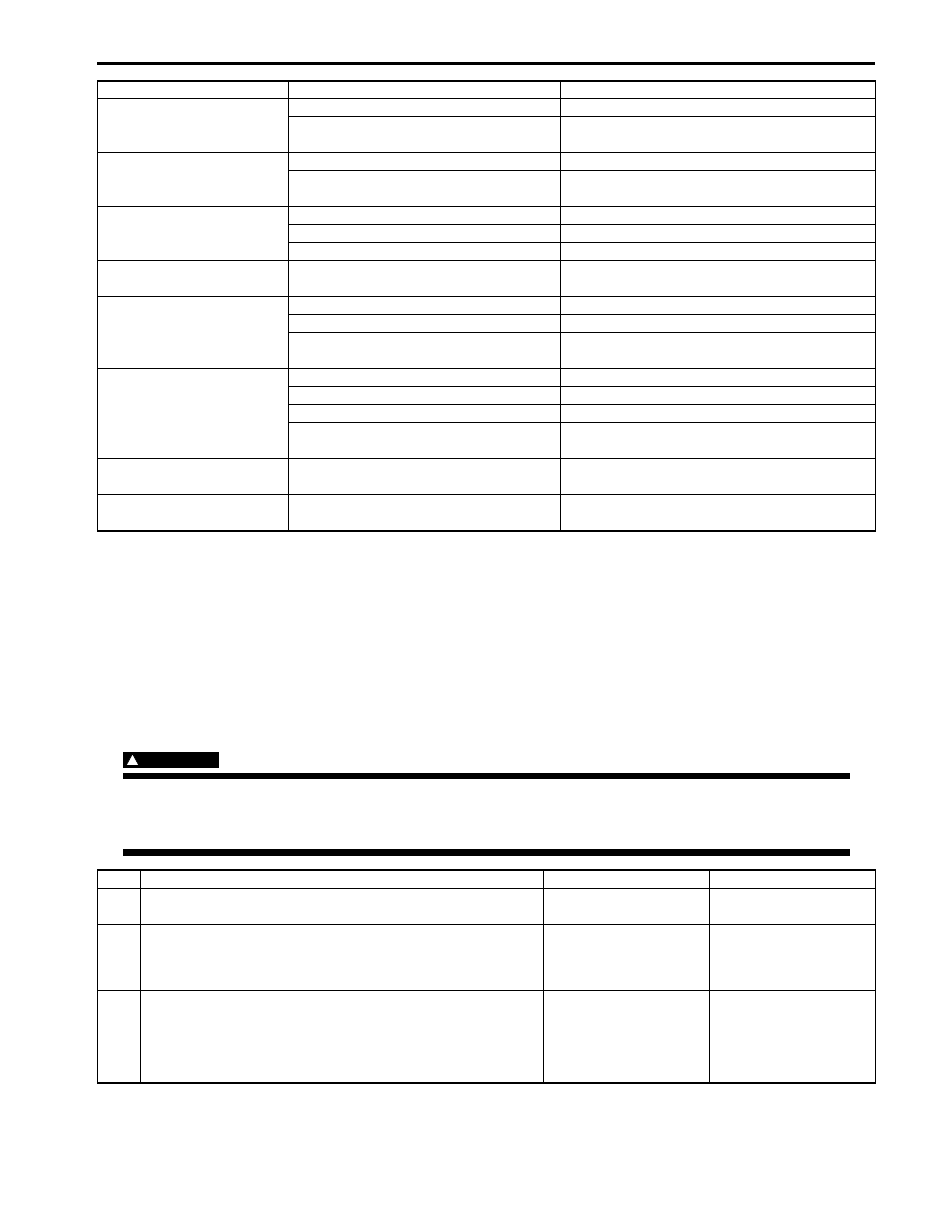
Automatic Transmission/Transaxle: 5A-43
No Gear Shift to 4th Gear
S5JB0A5104020
System Description
TCM does not shift to 5th gear under any of the following condition.
• “3” position switch signal is inputted.
• 4L/N switch is turned ON. (4L mode)
• TCM detects the following DTCs.
DTC, P0722, P0752, P0962, P0963, P0973, P0974, P0976, P0977, P1702
Troubleshooting
WARNING
!
• When performing a road test, select a place where there is no traffic or possibility of a traffic
accident and be very careful during testing to avoid occurrence of an accident.
• Road test should be carried out with 2 persons, a driver and tester, on a level road.
Poor 3
↔
O/D shift,
excessive shock or
slippage
Faulty O/D clutch
Inspect. If NG, replace.
Faulty O/D brake
Inspect. If NG, replace.
Poor 3
→
2 shift,
excessive shock or
slippage
Faulty direct clutch
Inspect. If NG, replace.
Faulty one-way clutch No.1
Inspect. If NG, replace.
Poor 2
→
1 shift,
excessive shock or
slippage
Faulty second brake
Inspect. If NG, replace.
Faulty one-way clutch No.1
Inspect. If NG, replace.
Faulty one-way clutch No.2
Inspect. If NG, replace.
Non operate TCC / lock-up
system
Faulty torque converter
Replace.
Excessive “N”
→
“D” time
lag
Faulty oil pump
Inspect. If NG, replace.
Faulty forward clutch
Inspect. If NG, replace.
Leakage from “D” range fluid pressure
circuit
Overhaul or replace valve body assembly.
Excessive “N”
→
“R” time
lag
Faulty oil pump
Inspect. If NG, replace.
Faulty direct clutch
Inspect. If NG, replace.
Faulty reverse brake
Inspect. If NG, replace.
Leakage from “R” range fluid pressure
circuit
Overhaul or replace valve body assembly.
Poor engine brake in
downshift to “2” range
Faulty 2nd coast brake
Inspect. If NG, replace.
Poor engine brake in
downshift to “L” range
Faulty reverse brake
Inspect. If NG, replace.
Condition
Possible cause
Correction / Reference Item
Step
Action
Yes
No
1
Was “A/T System Check” performed?
Go to Step 2.
Go to “A/T System
Check”.
2
Check DTC
Is DTC, P0722, P0752, P0962, P0963, P0973, P0974,
P0976, P0977 or P1702 detected?
Perform DTC Flow to
repair and retry.
Go to Step 3.
3
ECT check
1) Warm up engine to normal operating temperature.
2) Check ECT monitored by TCM using scan tool.
Is ECT indicated –40
°
C (–40
°
F)?
Go to Step 4.
Faulty ECT sensor, its
circuit or engine cooling
system. If OK, substitute
a known-good TCM and
recheck.
5A-44 Automatic Transmission/Transaxle:
No Lock-Up Occurs
S5JB0A5104021
System Description
TCM turns TCC pressure control solenoid OFF under any of the following conditions.
• Engine coolant temperature is lower than 60
°C (140 °F).
• 4L/N switch is turned ON. (4L mode)
• Brake light switch is turned ON. (Brake pedal is depressed)
• TCM detects the following DTCs.
P0712, P0713, P0717, P0722, P0962, P0963, P0973, P0974, P0976, P0977, P1702, P1703, P1774, P1777, P2763
and P2764
Troubleshooting
WARNING
!
• When performing a road test, select a place where there is no traffic or possibility of a traffic
accident and be very careful during testing to avoid occurrence of an accident.
• Road test should be carried out with 2 persons, a driver and tester, on a level road.
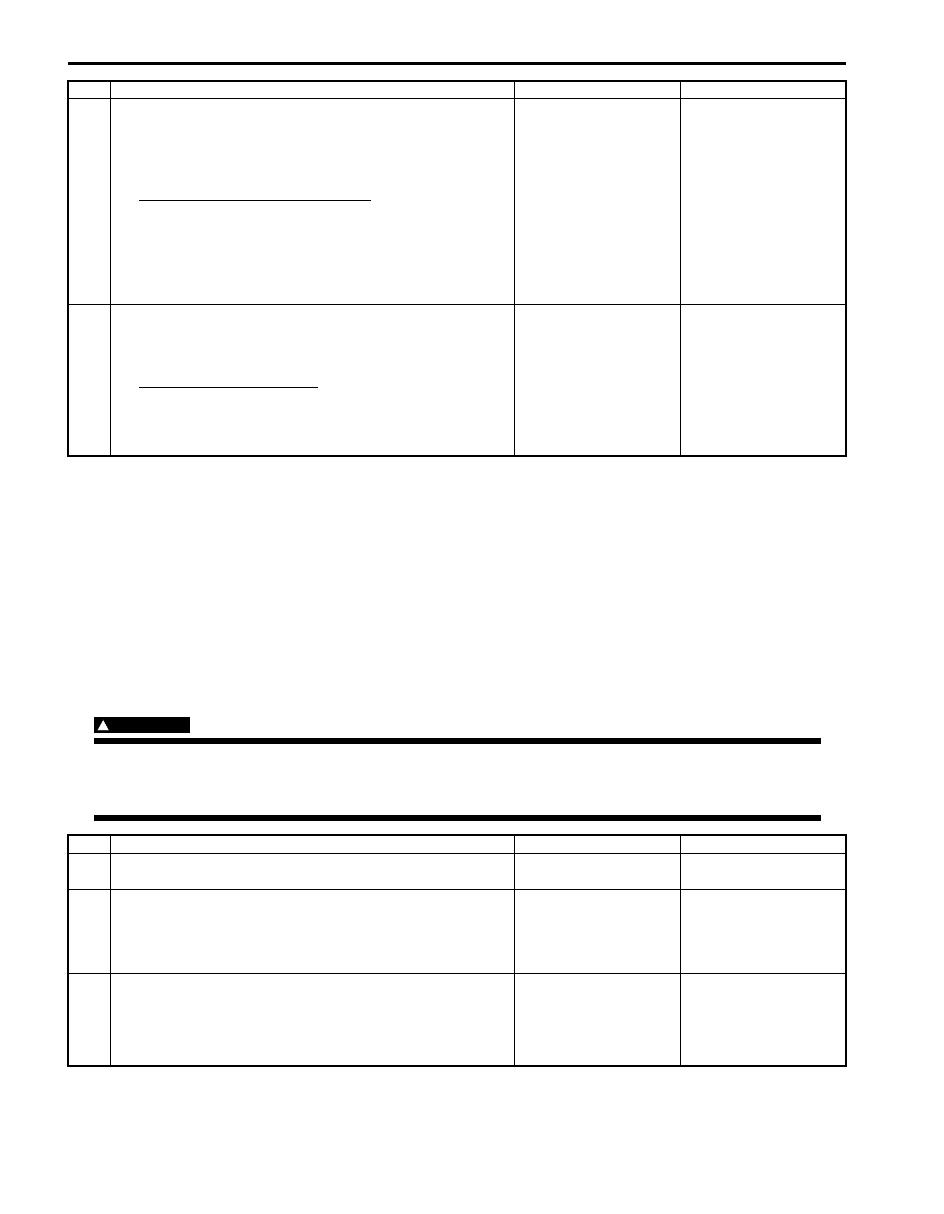
4
“3” position switch signal inspection
1) With ignition switch ON, check voltage between terminal
“E92-20” of TCM connector and ground under the
following conditions.
“3” position switch specification
Shift selector lever to “P”, “R”, “N” or “D” range: 2.9
– 3.8 V
Shift selector lever to “3”, “2” or “L” range: 1.4 – 2.0
V
Is result as specified?
Go to Step 5.
Faulty “3” position
switch or its circuit. If
OK, substitute a known-
good TCM and recheck.
5
4L/N switch signal inspection
1) With ignition switch ON, check voltage between terminal
“E93-4” of TCM connector and ground.
4L/N switch specification
Transfer gear position “4H”: Battery voltage
Transfer gear position “4L” or “N”: 0 – 2 V
Is result as specified?
Substitute a known-
good TCM and recheck.
Faulty 4L/N switch or its
circuit. If OK, substitute
a known-good TCM and
recheck.
Step
Action
Yes
No
Step
Action
Yes
No
1
Was “A/T System Check” performed?
Go to Step 2.
Go to “A/T System
Check”.
2
Check DTC
Is DTC P0712, P0713, P0717, P0722, P0962, P0963,
P0973, P0974, P0976, P0977, P1702, P1703, P1774,
P1777, P2763 or P2764 detected?
Perform DTC Flow to
repair and retry.
Go to Step 3.
3
ECT check
1) Warm up engine to normal operating temperature.
2) Check ECT using scan tool.
Is ECT more than 60
°
C (140
°
F)?
Go to Step 4.
Faulty ECT sensor, its
circuit or engine cooling
system. If OK, substitute
a known-good TCM and
recheck.

Automatic Transmission/Transaxle: 5A-45
Transmission Warning Light Circuit Check – Light Does Not Come “ON” at Ignition Switch ON
(Vehicle is equipped with engine diagnosis connector)
S5JB0A5104063
Troubleshooting
Transmission Warning Light Circuit Check – Light Remains “ON” at Ignition Switch ON (Vehicle is
equipped with engine diagnosis connector)
S5JB0A5104064
Troubleshooting
4
4L/N switch signal inspection
1) With ignition switch ON, check voltage between terminal
“E92-4” of TCM connector and ground.
4L/N switch specification
Transfer gear position or “4H”: Battery voltage
Transfer gear position “4L” or “N”: 0 – 2 V
Is result as specified?
Go to Step 5.
Faulty “4L” switch or its
circuit. If OK, substitute
a known-good TCM and
recheck.
5
Brake light switch signal inspection
1) With ignition switch ON, check voltage between terminal
“E61-34” of ECM connector and ground.
Brake light switch specification
Brake pedal is released: 0 – 1 V
Brake pedal is depressed: Battery voltage
Is result as specified?
Substitute a known-
good TCM and recheck.
Mis-adjusted brake light
switch, faulty brake light
switch or its circuit. If
OK, substitute a known-
good TCM and recheck.
Step
Action
Yes
No
Step
Action
Yes
No
1
Combination Meter Power Supply Check
1) Turn ignition switch ON.
Does other indicator / warning lights in combination meter
comes ON?
Go to Step 2.
Repair combination
meter power supply
circuit referring to
“Combination Meter
Circuit Diagram in
Section 9C”.
2
1) TCM power and ground circuit check referring to “TCM
Power and Ground Circuit Check”.
Is it in good condition?
Go to Step 3.
Repair or replace.
3
DTC check
1) Check DTC referring to “DTC Check”.
Is there DTC P1774 or P1775?
Go to applicable DTC
diag. flow.
Go to Step 4.
4
Combination Meter Function Check
1) Turn ignition switch ON.
Does A/T selector position indicator show correct select
lever position?
Replace combination
meter.
Substitute a known-
good TCM and recheck.
Step
Action
Yes
No
1
Diagnostic Trouble Code (DTC) Check
1) Check DTC referring to “DTC Check”.
Is there any DTC(s)?
Perform DTC Flow to
repair and retry.
Substitute a known-
good TCM and recheck.
If OK, substitute a
known-good
combination meter and
recheck.
Нет комментариевНе стесняйтесь поделиться с нами вашим ценным мнением.
Текст