Suzuki Grand Vitara JB416 / JB420. Manual — part 223
5A-26 Automatic Transmission/Transaxle:
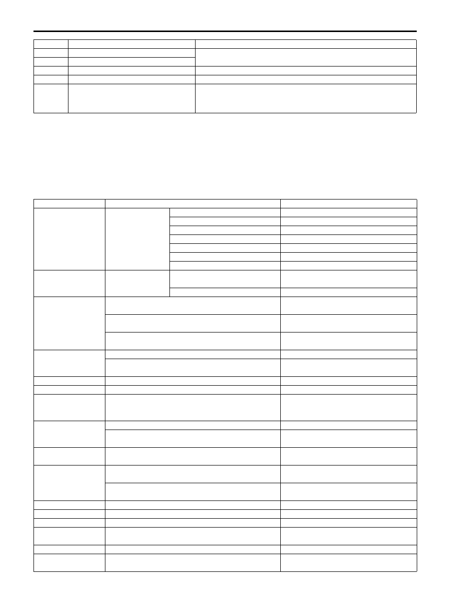
Scan Tool Data
S5JB0A5104009
As the data values given in the following table are standard values estimated on the basis of values obtained from the
normally operating vehicles by using a scan tool, use them as reference value. Even when the vehicle is in good
condition, there may be cases where the checked value does not fall within each specified data range. Therefore,
judgment as abnormal should not be made by checking with these data alone.
Also, condition in the following table that can be checked by the scan tool are those detected by TCM and output from
TCM as commands and there may be cases where the automatic transmission or actuator is not operating (in the
condition) as indicated by the scan tool.
P1874 4L switch circuit malfunction (Short)
Slip controlled lock-up function is inhibited to operate.
P1875 4L switch circuit malfunction (Open)
P1878 Torque Converter Clutch Shudder
Slip controlled lock-up function is inhibited to operate.
P2763 Torque Converter Clutch Circuit High Power supply for TCC pressure control solenoid is cut.
P2764
Torque Converter Clutch Circuit Low
• Lock-up function is inhibited to operate.
• When vehicle speed is less than 10 km/h (6 mile/h), gear
position is fixed in 1st gear for prevention of engine stall.
Scan Tool Data
Vehicle Condition
Normal Condition / Reference Values
Gear Position
Ignition switch ON
POWER mode
OFF
Select lever is in “P” position
P/N
Select lever is in “R” position
R
Select lever is in “N” position
P/N
Select lever is in “D” position
1st
Select lever is in “3” position
1st
Select lever is in “2” position
1st
Select lever is in “L” position
1st
Throttle Position
Ignition switch ON Accelerator pedal is depressed
0 – 100% (varies depending on
depressed value)
Accelerator pedal is released
0 – 5%
Input Shaft Rev
At engine idle speed and selector lever is in “P”
position
(Engine idle speed is displayed in
increments of 50 rpm)
At 40 km/h (25 mile/h) constant speed, 20% or less
throttle opening and 3rd gear (“3” range)
2300 RPM
(displayed in increments of 50 rpm)
At 60 km/h (37.5 mile/h) constant speed, 20% or less
throttle opening and 4th gear (“D” range)
0 RPM
Output Shaft Rev
At vehicle stop
0 RPM
At 40 km/h (25 mile/h) constant speed, 20% or less
throttle opening and 3rd gear (“3” range)
2300 RPM
(displayed in increments of 50 rpm)
Vehicle Speed 1
At vehicle stop
0 km/h, 0 MPH
Battery Voltage
Ignition switch ON and engine stop
Battery voltage is displayed (8 – 16 V)
ATF Temp
After driving at 60 km/h (37.5 mile/h) for 15 minutes
or more, and A/T fluid temperature around sensor
reaches 70 – 80
°C (158 – 176 °F)
70 – 80 °C (158 – 176 °F)
TCC Sol Duty
At vehicle stop, closed throttle and 1st gear
0%
At 80 km/h (50 mile/h) constant speed, 30% or less
throttle opening and 3th gear. (“3” range)
100%
Press Cont Sol
At vehicle stop, closed throttle, engine idle speed and
1st gear
9.5%
Slip RPM
Engine running at idle speed and selector lever is in
“P” range
0
±25 RPM
Engine running, vehicle stop and selector lever is in
“D” range
Engine speed is displayed
Vehicle Speed 2
At vehicle stop
0 km/h, 0 MPH
Engine Speed
At engine idle speed
Engine idle speed is displayed
Coolant Temp
Ignition switch ON
Engine coolant temperature is displayed
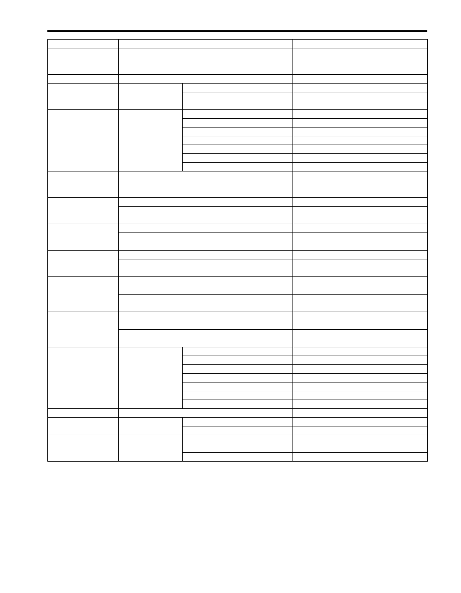
Target Engine
Torque
Ignition switch ON
0 N
⋅m
Engine Torque
Ignition switch ON
0 N
⋅m
MIL request (for E-
OBD)
Ignition switch ON
OFF
DTC No.
Trouble Area
Fail Safe Operation
Automatic Transmission/Transaxle: 5A-27
Malfunction
Indication On (for
Non E-OBD)
Ignition switch ON
OFF
Fuel Cut Flag
Ignition switch ON
OFF
O/D Off Switch
Ignition switch ON Shift selector lever to “3” range
ON
Shift selector lever to other
above range
OFF
Trans Range
Ignition switch ON Select lever is in “P” position
P
Select lever is in “R” position
R
Select lever is in “N” position
N
Select lever is in “D” position
D
Select lever is in “3” position
D
Select lever is in “2” position
2
Select lever is in “L” position
L
Shift Sol A Con
At vehicle stop, closed throttle and 1st gear
ON
At 60 km/h (37.5 mile/h) constant speed, 20% or less
throttle opening and 3rd gear
OFF
Shift Sol A Mon
At vehicle stop, closed throttle and 1st gear
ON
At 60 km/h (37.5 mile/h) constant speed, 20% or less
throttle opening and 3rd gear
OFF
Shift Sol B Con
At vehicle stop, closed throttle and 1st gear
OFF
At 20 km/h (12.5 mile/h) constant speed, 20% or less
throttle opening and 2nd gear
ON
Shift Sol B Mon
At vehicle stop, closed throttle and 1st gear
OFF
At 20 km/h (12.5 mile/h) constant speed, 20% or less
throttle opening and 2nd gear
ON
Mode Select Switch Ignition switch ON, P/N mode switch is at Normal
position
NORMAL
Ignition switch ON, P/N mode switch is at Power
position
POWER
4WD Low Switch
Ignition switch ON, transfer position switch is “4H”
position
OFF
Ignition switch ON, transfer position switch is “4L”
position
ON
D Range Signal
Ignition switch ON Select lever is in “P” position
P/N range
Select lever is in “R” position
D range
Select lever is in “N” position
P/N range
Select lever is in “D” position
D range
Select lever is in “3” position
D range
Select lever is in “2” position
D range
Select lever is in “L” position
D range
A/C Switch
Ignition switch ON and air conditioner switch OFF
Cancel
Brake Switch
Ignition switch ON Brake pedal is depressed
ON
Brake pedal is released
OFF
Accel Actual Pos
Ignition switch ON Accelerator pedal is depressed
0 – 100% (varies depending on
depressed value)
Accelerator pedal is released
0%
Scan Tool Data
Vehicle Condition
Normal Condition / Reference Values

5A-28 Automatic Transmission/Transaxle:
Scan Tool Data Definitions
Gear Position (1
ST
, 2
ND
, 3
RD
, 4
TH
, N, R): This
parameter is indicated actual gear position.
Throttle Position (%): Throttle valve opening ratio sent
from ECM on CAN communication line.
Input Shaft Rev (RMP): Input shaft revolution
computed by reference pulses coming from input
shaft speed sensor on transmission case.
Output Shaft Rev (RMP): Output shaft revolution
computed by reference pulses coming from output
shaft speed sensor on transmission case.
Vehicle Speed 1 (Km/h): This parameter is competed
by output shaft speed sensor and 4WD low switch on
TCM. Gear shift schedule relate this parameter.
Battery Voltage (V): Battery voltage read by TCM as
analog input signal by TCM.
ATF Temp (
°C): ATF temperature detected by signal
from transmission fluid temperature sensor installed
in valve body.
TCC Sol Duty (%): Electric current value ration
between electric current value being outputted from
TCM to TCC pressure control solenoid and
maximum value can be outputted by TCM.
Press Cont Sol (%): Electric current value ratio
between electric current value being outputted from
TCM to pressure control solenoid-A and maximum
value can be outputted by TCM.
Slip RPM (RMP): This parameter indicates slipping
rotation in the torque converter (difference between
input shaft rotation and engine rotation).
Vehicle Speed 2 (Km/h): Actual vehicle speed
detected by signal on CAN communication line fed
from ECM.
Engine Speed (RPM): Engine speed computed by
signal on CAN communication line fed from ECM.
Coolant Temp (
°C): Engine coolant temperature
detected by signal on CAN communication line fed
from ECM.
Target Engine Torque (N
⋅m): Target engine torque
detected by signal on CAN communication line fed
from ECM.
Engine Torque (N
⋅m): Actual engine torque detected
by signal on CAN communication line fed from ECM.
MIL Request (ON, OFF) (for E-OBD model): ON:
Signal which TCM requires combination meter to
turn ON malfunction indicator lamp.
OFF: Signal which TCM does not require
combination meter to turn ON malfunction indicator
lamp.
Malfunction Indication On (ON, OFF) (for non E-OBD
model): ON: Signal which TCM requires
combination meter to turn ON transmission warning
lamp.
OFF: Signal which TCM does not require
combination meter to turn ON transmission warning
lamp.
Fuel Cut Flag: ON: Signal which inform that fuel cut is
operating.
OFF: Signal which inform that fuel cut is not
operating.
O/D Off Switch (ON, OFF): Inputted signal from “3”
position switch in selector lever assembly.
ON: Shift selector lever to “3” range
OFF: Shift selector lever to other above range
Trans Range (P, R, N, D, 2, L): It indicates
transmission range according to transmission range
switch signal.
Shift Sol A Con/ MON (ON, OFF): COM-ON: ON
command being outputted to shift solenoid-A.
COM-OFF: OFF command not being outputted to
shift solenoid-A.
MON-ON: Electricity being passed to shift solenoid-
A.
MON-OFF: Electricity not being passed to shift
solenoid-A.
Shift Sol B Con / MON (ON, OFF): COM-ON: ON
command being outputted to shift solenoid-B.
COM-OFF: OFF command not being outputted to
shift solenoid-B.
MON-ON: Electricity being passed to shift solenoid-
B.
MON-OFF: Electricity not being passed to shift
solenoid-B.
Mode Select Switch (NORMAL, POWER): Inputted
signal from P/N mode switch on center console.
NORMAL: P/N mode switch is at OFF position.
POWER: P/N mode switch is at ON position.
4WD Low Switch (ON, OFF): Inputted signal from 4L/
N switch on transfer case.
ON: Transfer gear position is 4L
OFF: Transfer gear position is 4H
D RANGE SIGNAL (P/N range, D range): ON: Signal
which TCM require ECM to increase idle speed
OFF: Signal which TCM does not require ECM to
increase idle speed
A/C Switch (ON, OFF): ON: Signal which inform that
air conditioner compressor is turned ON.
OFF: Signal which inform that air conditioner
compressor is turned OFF.
Brake Switch (ON, OFF): Brake light switch position
detected by signal on CAN communication line fed
from ECM.
ON: Brake pedal depressed
OFF: Brake pedal released
Accel Actual Pos (%): Accelerator pedal opening ratio
detected by signal on CAN communication line fed
from ECM.
Automatic Transmission/Transaxle: 5A-29
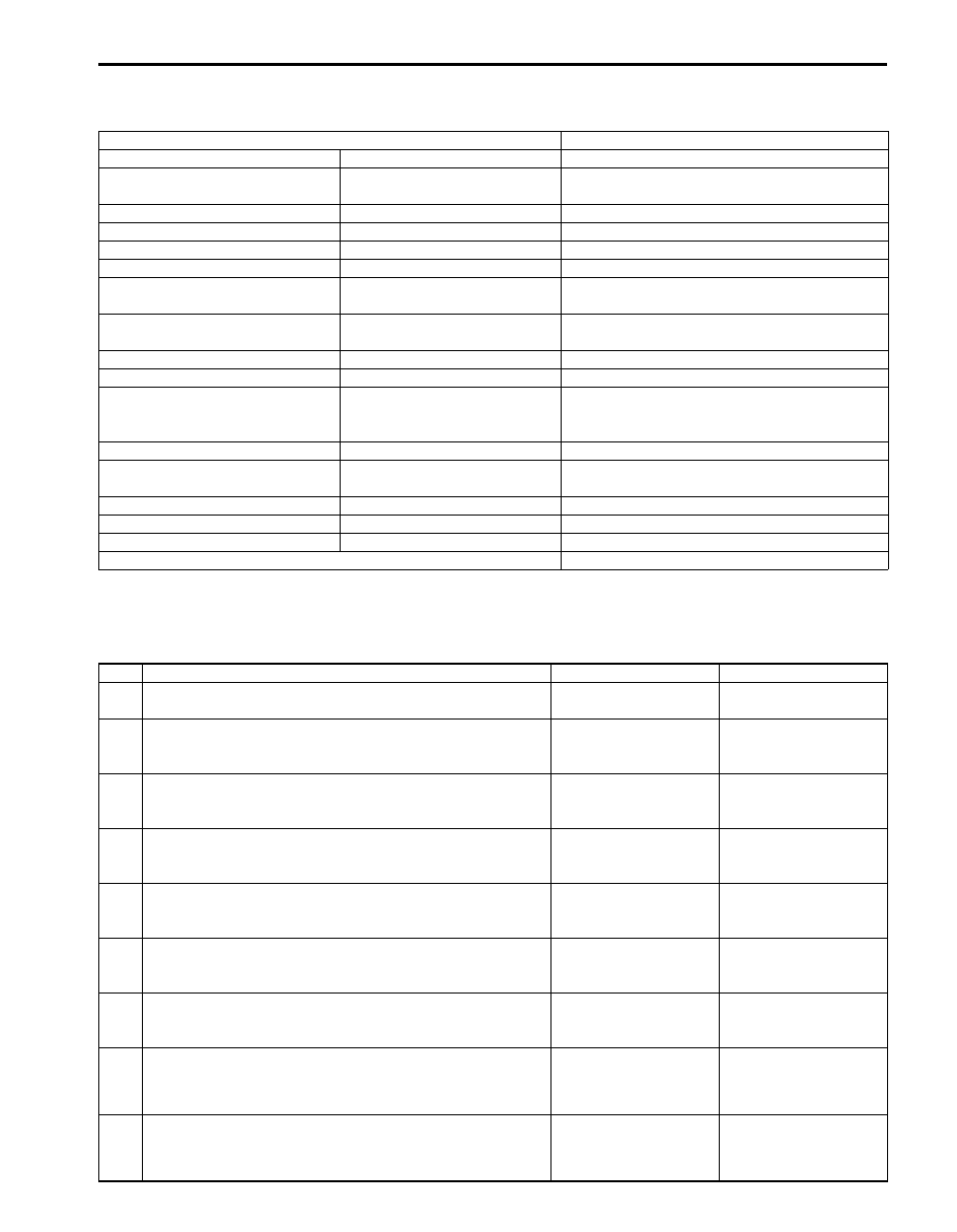
Visual Inspection
S5JB0A5104010
Visually check the following parts and systems.
A/T Basic Check
S5JB0A5104011
This check is important for troubleshooting when TCM has detected no DTC and no abnormality has been noted in
visual inspection. Follow the flow table carefully.
Inspection Item
Referring
A/T fluid
Level, leakage, color
A/T fluid hoses
Disconnection, looseness,
deterioration
“Oil Cooler Hose and Pipe Components”
A/T select cable
Installation, operation
Engine oil
Level, leakage
“Engine Oil and Filter Change in Section 0B”
Engine coolant
Level, leakage
“Engine Coolant Change in Section 0B”
Battery
Fluid level, corrosion of terminal
Connectors of electric wire harness Disconnection friction
“Intermittent and Poor Connection Inspection in
Section 00”
Fuses
Burning
“Cautions in Body Electrical System Servicing in
Section 9A”
Parts
Installation, damage
Bolt
Looseness
Transmission warning light
Operation at engine start
“Transmission Warning Light Operation Check
(Vehicle is Equipped with Engine Diagnosis
Connector)”
“POWER” lamp
Operation at engine start
““POWER” Lamp Operation Check”
Malfunction indicator lamp
Operation at engine start
“Malfunction Indicator Lamp (MIL) Check in
Section 1A”
Charge warning lamp
Operation at engine start
“Generator Symptom Diagnosis in Section 1J”
Engine oil pressure warning lamp
Operation at engine start
“Oil Pressure Switch Inspection in Section 9C”
Engine coolant temp. meter
Operation at engine start
Other parts that can be checked visually
Step
Action
Yes
No
1
Was “A/T System Check” performed?
Go to Step 2.
Go to “A/T System
Check”.
2
Perform “Road Test”
Is it OK?
Go to Step 3.
Proceed to
“Troubleshooting” in
“Road Test”.
3
Perform “Manual Road Test”
Is it OK?
Go to Step 4.
Proceed to
“Troubleshooting” in
“Manual Road Test”.
4
Perform “Engine Brake Test”
Is it OK?
Go to Step 5.
Proceed to
“Troubleshooting” in
“Engine Brake Test”.
5
Perform “Stall Test”
Is it OK?
Go to Step 6.
Proceed to
“Troubleshooting” in
“Stall Test”.
6
Perform “Time Lag Test”
Is it OK?
Go to Step 7.
Proceed to
“Troubleshooting” in
“Time Lag Test”.
7
Perform “Line Pressure Test”
Is it OK?
Go to Step 8.
Proceed to
“Troubleshooting” in
“Line Pressure Test”.
8
1) Proceed to “Trouble Diagnosis 1” in “A/T Symptom
Is trouble identified?
Repair or replace faulty
parts.
Go to Step 9.
9
1) Proceed to “Trouble Diagnosis 2” in “A/T Symptom
Is trouble identified?
Repair or replace faulty
parts.
Proceed to “Trouble
Diagnosis 3” in “A/T
Symptom Diagnosis”.
Нет комментариевНе стесняйтесь поделиться с нами вашим ценным мнением.
Текст