Suzuki Grand Vitara JB416 / JB420. Manual — part 87

1D-16 Engine Mechanical: For M16A Engine with VVT
17) With hose connected, detach A/C compressor from
its bracket (if equipped) referring to “Compressor
Assembly Removal and Installation for M16 Engine
Model in Section 7B”.
CAUTION
!
Suspend removed A/C compressor at a place
where no damage will be caused during
removal and installation of engine assembly.
18) Support front suspension frame and engine rear
mounting member using jack (2).
19) Carry out Step 1) to 12) of “Removal” under “Front
Suspension Frame, Stabilizer Bar and/or Bushings
Removal and Installation in Section 2B” in order to
lower engine with front suspension frame.
20) Remove front suspension frame mounting bolt (1).
21) Remove engine rear mounting member bolt (1).
22) Before lowering engine with transmission and front
suspension frame from engine compartment,
recheck to make sure all hoses, electric wires and
cables are disconnected from engine.
23) Lower engine with transmission and front
suspension frame from engine compartment.
CAUTION
!
Before lowering engine, in order to avoid
damage to A/C compressor and P/S pump,
make clearance by rising them.
24) Disconnect transmission from engine referring to
“Manual Transmission Assembly Dismounting and
Remounting in Section 5B”, if necessary.
25) Remove engine with engine front mounting bracket
(1) from engine front mounting (2), if necessary.
26) Remove clutch cover and clutch disc referring to
“Clutch Cover, Clutch Disc and Flywheel Removal
and Installation in Section 5C”, if necessary.
1
2
I5JB0A141017-02
I5JB0A141018-02
I5JB0A141019-01

Engine Mechanical: For M16A Engine with VVT 1D-17
Installation
1) Install clutch cover and clutch disc referring to
“Clutch Cover, Clutch Disc and Flywheel Removal
and Installation in Section 5C”, if necessary.
2) Install engine with engine front mounting bracket to
engine front mounting.
For tightening torque, refer to “Engine Mountings
Components: For M16A Engine with VVT”, if
necessary.
3) Connect transmission to engine referring to “Manual
Transmission Assembly Dismounting and
Remounting in Section 5B”, if necessary.
4) Lift engine with transmission and front suspension
frame into engine compartment with jack.
CAUTION
!
Before lifting engine, in order to avoid
damage to A/C compressor and P/S pump,
make clearance by rising them.
5) Tighten engine rear mounting member bolt referring
to “Engine Mountings Components: For M16A
Engine with VVT”.
6) Carry out Step 5) to 19) of “Installation” under “Front
Suspension Frame, Stabilizer Bar and/or Bushings
Removal and Installation in Section 2B” in order to lift
engine with front suspension frame.
7) Remove engine jack.
8) Install front and rear propeller shafts referring to
“Propeller Shaft Removal and Installation in Section
3D”.
9) Install exhaust No.1, No.2 and center pipes referring
to “Exhaust System Components in Section 1K”.
10) Install A/C compressor to its bracket (if equipped)
referring to “Compressor Assembly Removal and
Installation for M16 Engine Model in Section 7B”.
11) Install P/S pump to its bracket (if equipped) referring
to “P/S Pump Removal and Installation for M16
Engine Model in Section 6C”.
12) Return disconnected hoses, cables and electric
wires noting the followings.
• Tighten nuts to specified torque.
Tightening torque
Starting motor terminal nut: 11 N·m (1.1 kgf-m,
8.0 lb-ft)
Generator terminal nut: 7 N·m (0.7 kgf-m, 5.0 lb-
ft)
13) Install P/S pump and A/C compressor (if equipped)
drive belt referring to “P/S Pump and A/C
Compressor (If Equipped) Drive Belt Removal and
Installation for M16 Engine Model in Section 6C”.
14) Adjust P/S pump and A/C compressor (if equipped)
drive belt tension referring to “P/S Pump and A/C
Compressor (If Equipped) Drive Belt Inspection and
Adjustment for M16 Engine Model in Section 6C”.
15) Install air cleaner case (2).
16) Connect MAF sensor connector (1).
17) Install air intake pipe (2).
18) Connect breather union (1) to air intake pipe (2).
19) Check all removed parts are back in place.
20) Refill cooling system with coolant referring to
“Cooling System Flush and Refill in Section 1F”.
21) Refill engine with engine oil referring to “Engine Oil
and Filter Change in Section 0B”.
22) Install engine hood after disconnecting windshield
washer hose.
23) After installation, bleed air from clutch system.
Refer to “Air Bleeding of Brake System in Section
4A” for air bleeding procedure.
24) Connect negative cable at battery.
25) With engine OFF, turn ignition switch to ON position
and check for fuel leakage.
26) Start engine and check coolant oil and exhaust gas
leakage at each connection.
2
1
I5JB0A141004-02
1
2
I5JB0A141008-03

1D-18 Engine Mechanical: For M16A Engine with VVT
Timing Chain Cover Components
S5JB0A1416014
I5JB0A141020-02
1. Crankshaft pulley bolt
9. Oil gallery pipe No.1
17. Oil control valve
2. Crankshaft pulley
10. Copper washer
: 11 N
⋅m (1.1 kgf-m, 8.0 lb-ft)
3. Oil seal
: Apply engine oil to oil seal lip.
11. Oil gallery pipe No.1 bolt
: 25 N
⋅m (2.5 kgf-m, 18.0 lb-ft)
4. Timing chain cover
: Apply sealant 99000-31140 to the mating surface
of cylinder and cylinder head.
: Apply sealant 99000-31260 to the mating surface
of timing chain cover referring to the figure of Step 5)
of “Installation” under “Timing Chain Cover Removal
and Installation: For M16A Engine with VVT”.
12. Oil gallery pipe No.2
: 30 N
⋅m (3.0 kgf-m, 22.0 lb-ft)
5. Pin
13. Oil gallery pipe No.2 bolt
: 150 N
⋅m (15.0 kgf-m, 108.5 lb-ft)
6. Oil control valve mounting nut
14. Oil gallery pipe No.3
: Do not reuse.
7. Timing chain cover mounting bolts
15. Oil gallery pipe No.3 bolt
8. Timing chain cover mounting nut
16. O-ring
: Apply engine oil.
Engine Mechanical: For M16A Engine with VVT 1D-19
Timing Chain Cover Removal and Installation
S5JB0A1416015
CAUTION
!
• Keep working table, tools and hands clean
while overhauling.
• Use special care to handle aluminum parts
so as not to damage them.
• Do not expose removed parts to dust.
Keep them always clean.
Removal
1) Remove engine assembly from vehicle referring to
“Engine Assembly Removal and Installation: For
M16A Engine with VVT”.
2) Remove P/S pump and A/C compressor (if
equipped) drive belt referring to “P/S Pump and A/C
Compressor (If Equipped) Drive Belt Removal and
Installation for M16 Engine Model in Section 6C”.
3) Remove water pump and generator drive belt
referring to “Water Pump and Generator Drive Belt
Removal and Installation (For M16 Engine) in
Section 1J”.
4) Remove crankshaft pulley bolt.
To lock crankshaft pulley (1), use special tool with it
as shown in the figure.
Special tool
(A): 09917–68221
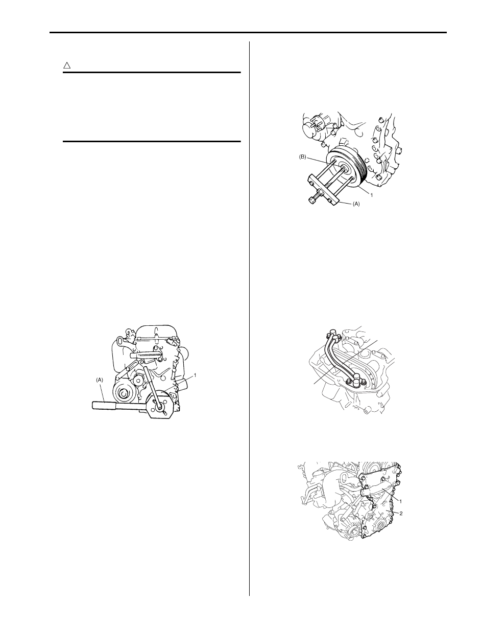
5) Remove crankshaft pulley (1).
If it is hard to remove, use special tools as shown in
the figure.
Special tool
(A): 09944–36011
(B): 09926–58010
6) Remove cylinder head cover referring to “Cylinder
Head Cover Removal and Installation: For M16A
Engine with VVT”.
7) Remove oil pan referring to “Oil Pan and Oil Pump
Strainer Removal and Installation: For M16A Engine
with VVT in Section 1E”.
8) Remove water pump pulley.
9) Remove A/C compressor bracket and P/S pump
bracket from cylinder block.
10) Remove oil gallery pipes No.2 (1) and No.3 (2).
11) Remove water outlet pipe (1) from timing chain
cover.
12) Remove timing chain cover (2).
13) Remove oil control valve from timing chain cover
referring to “Oil Control Valve Removal and
Installation: For M16A Engine with VVT”, if
necessary.
I5JB0A141021-01
I2RH0B140052-01
1
2
I3RH0B140021-01
I5JB0A141022-01
Нет комментариевНе стесняйтесь поделиться с нами вашим ценным мнением.
Текст