Suzuki Grand Vitara JB416 / JB420. Manual — part 137

1J-6 Charging System:
Repair Instructions
Jump Starting in Case of Emergency
S5JB0A1A06004
With Auxiliary (Booster) Battery
CAUTION
!
If vehicle is manual transmission model and
has a catalytic converter, do not push or tow
it to start. Damage to its emission system
and/or to other parts may result.
Both booster and discharged battery should be treated
carefully when using jumper cables. Follow the
procedure outlined as follows, being careful not to cause
sparks.
WARNING
!
• Departure from these conditions or
procedure described as follows could
result in:
a. Serious personal injury (particularly to
eyes) or property damage from such
causes as battery explosion, battery
acid, or electrical burns.
b. Damage to electronic components of
either vehicle.
• Never expose battery to open flame or
electric spark. Batteries generate gas
which is flammable and explosive.
• Remove rings, watches, and other jewelry.
Wear approved eye protection.
• Do not allow battery fluid to contact eyes,
skin, fabrics, or painted surface as fluid is
a corrosive acid. Flush any contacted area
with water immediately and thoroughly.
• Be careful so that metal tools or jumper
cables do not contact positive battery
terminal (or metal in contact with it) and
any other metal on vehicle, because a
short circuit could occur.
• Batteries should always be kept out of
reach of children.
1) Set parking brake and place automatic transmission
in PARK (NEUTRAL on manual transmission).
2) Turn OFF ignition switch, turn OFF lights and all
other electrical loads.
3) Check built-in indicator (if equipped). If it is clear or
light yellow, replace the battery.
4) Attach end of one jumper cable to positive terminal
of booster battery and the other end of the same
cable to positive terminal of discharged battery. (Use
12-volt battery only to jump start engine).
5) Attach one end of the remaining negative cable to
negative terminal of booster battery, and the other
end to a solid engine ground (such as exhaust
manifold) at least 45 cm (18 in.) away from battery of
vehicle being started.
WARNING
!
Do not connect negative cable directly to
negative terminal of dead battery.
6) Start engine of vehicle with booster battery and turn
off electrical accessories. Then start engine of the
vehicle with discharged battery.
7) Disconnect jumper cable in the exact reverse order.
With Charging Equipment
CAUTION
!
When jump starting engine with charging
equipment, be sure equipment used is 12-
volt and negative ground. Do not use 24-volt
charging equipment. Using such equipment
can cause serious damage to electrical
system or electronic parts.

Charging System: 1J-7
Battery Dismounting and Remounting
S5JB0A1A06005
WARNING
!
When handling battery, following safety
precautions should be followed:
• Hydrogen gas is produced by battery. A
flame or spark near battery may cause the
gas to ignite.
• Battery fluid is highly acidic. Avoid spilling
on clothing or other fabric. Any spilled
electrolyte should be flushed with large
quantity of water and cleaned immediately.
Dismounting
1) Disconnect negative cable.
2) Disconnect positive cable.
3) Remove retainer.
4) Remove battery.
Handling
When handling battery, the following safety precautions
should be followed:
• Hydrogen gas is produced by battery. A flame or
spark near battery may cause the gas to ignite.
• Battery fluid is highly acidic. Avoid spilling on clothing
or other fabric. Any spilled electrolyte should be
flushed with large quantity of water and cleaned
immediately.
Remounting
1) Reverse removal procedure.
2) Tighten battery cables securely.
NOTE
Check to be sure that ground cable has
enough clearance to hood panel by terminal.
Water Pump and Generator Drive Belt Removal
and Installation (For M16 Engine)
S5JB0A1A06011
Removal
1) Disconnect negative cable at battery.
2) If vehicle equipped with A/C, remove compressor
drive belt before removing water pump belt (1).
Refer to “P/S Pump and A/C Compressor (If
Equipped) Drive Belt Removal and Installation for
M16 Engine Model in Section 6C”.
3) Loosen drive belt adjusting bolt (2) and generator
pivot bolt (3).
4) Loosen water pump and generator drive belt
adjuster bolt (4) to displace generator and then
remove water pump belt.
Installation
1) Install belt (1) to water pump pulley (2), crankshaft
pulley (3) and generator pulley (4).
2) Adjust belt tension by referring to “Water Pump and
Generator Drive Belt Tension Inspection and
Adjustment (For M16 Engine)”.
3) If vehicle equipped with A/C, install compressor drive
belt referring to “P/S Pump and A/C Compressor (If
Equipped) Drive Belt Removal and Installation for
M16 Engine Model in Section 6C”.
4) Connect negative cable at battery.
1. Battery
4. Body ground bolt
2. Positive cable
5. Retainer
3. Negative cable
6. Nut
3
6
5
2
4
1
I5JB0A1A0007-01
4
2
3
1
I5JB0A1A0001-01
4
2
1
3
I5JB0A1A0002-01
1J-8 Charging System:
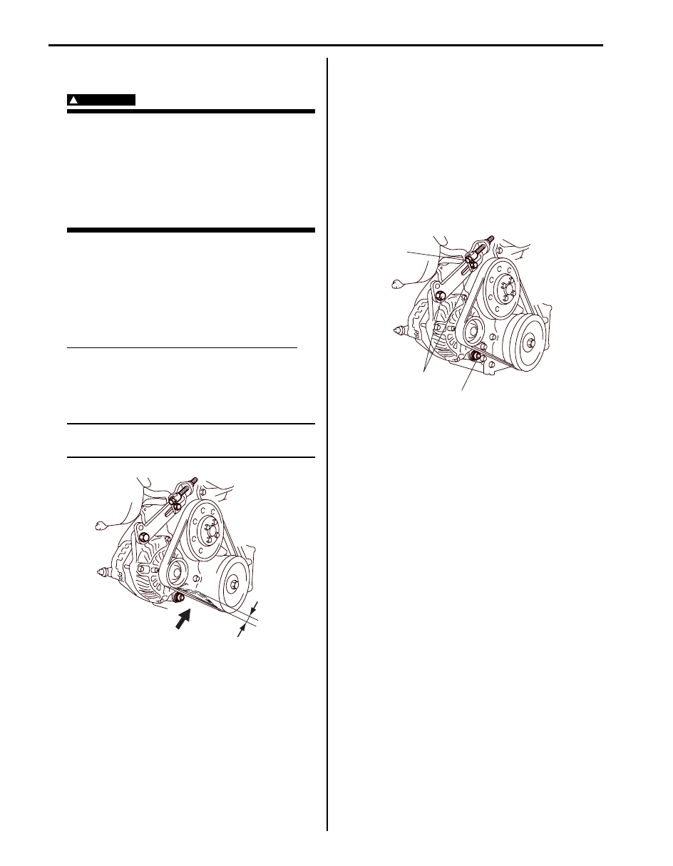
Water Pump and Generator Drive Belt Tension
Inspection and Adjustment (For M16 Engine)
S5JB0A1A06012
WARNING
!
• Disconnect negative cable at battery
before checking and adjusting belt
tension.
• To help avoid danger of being burned, do
not remove radiator cap while engine and
radiator are still hot. Scalding fluid and
steam can be blown out under pressure if
cap is taken off too soon.
1) Inspect belt for cracks, cuts, deformation, wear and
cleanliness. If it is necessary to replace belt, refer to
“Water Pump and Generator Drive Belt Removal and
Installation (For M16 Engine)”.
2) Check belt for tension. Belt is in proper tension when
it deflects the following specification under thumb
pressure (about 10 kg or 22 lb.).
Water pump / generator drive belt tension “a”
Existing belt: 7.0 – 8.5 mm (0.28 – 0.33 in.) as
deflection / 10 kg (22 lbs)
New belt: 5.5 – 6.5 mm (0.22 – 0.26 in.) as
deflection / 10 kg (22 lbs)
NOTE
When replacing belt with a new one, adjust
belt tension to 5.5 – 6.5 mm (0.22 – 0.26 in.).
3) If belt is too tight or too loose, adjust it to proper
tension by displacing generator position.
4) To adjust belt tension, loosen generator adjusting
bolt (3) and displace generator position by loosening
on tightening adjuster bolt.
5) Tighten generator adjusting bolt (1) and pivot bolts
(2) as specified torque.
Tightening torque
Generator adjusting bolt (a): 25 N·m (2.5 kgf-m,
18.5 lb-ft)
Generator pivot bolt (b): 52.5 N·m (5.25 kgf-m,
38.0 lb-ft)
6) Check belt for tension after turn crankshaft two
rotations clockwise.
7) Tightening generator adjuster bolt (3) as specified
torque.
Tightening torque
Generator adjuster bolt (c): 7.0 N·m (0.7 kgf-m,
5.0 lb-ft)
8) Connect negative cable at battery.
“a”
I5JB0A1A0008-01
1, (a)
2, (b)
3, (C)
I5JB0A1A0009-01

Charging System: 1J-9
Water Pump and Generator Drive Belt On-Vehicle Inspection (For J20 Engine)
S5JB0A1A06013
[Type A]
1) Disconnect negative cable at battery.
2) Inspect belt for cracks, cuts, deformation, wear and cleanliness. If any of above conditions are found, replace belt,
referring to “Water Pump and Generator Drive Belt Removal and Installation (For J20 Engine)”.
3) Make sure that tension indicator “A” is within the range “a”.
If indicator “A” comes into the NG range “c” passing “b”, replace generator belt with a new one.
NOTE
Use mirror when checking belt tension.
[Type B]
• Inspect belt for cracks, cuts, deformation, wear and cleanliness. If any of these conditions are found, replace belt,
referring to “Water Pump and Generator Drive Belt Removal and Installation (For J20 Engine)”.
• Check to make sure that tension indicators are as follows in the figure by using mirror.
a. If the tension indicator “B” is found to the left of the indicator “A”, replace the generator belt.
b. If new generator belt has been installed, indicator “A” should be within “a” of the figure.
If it isn’t, it means that belt is not installed properly.
Reinstall it properly.
I1SQ01020003-01
I5JB0A1A0010-01
1. Water pump and generator drive belt
3. Water pump pulley
5. Tensioner
2. Crankshaft pulley
4. Tension pulley
6. Power steering pump pulley
Нет комментариевНе стесняйтесь поделиться с нами вашим ценным мнением.
Текст