Suzuki Grand Vitara JB416 / JB420. Manual — part 82
1C-13 Engine Electrical Devices:
Mass Air Flow (MAF) and Intake Air
Temperature (IAT) Sensor On-Vehicle
Inspection
S5JB0A1306019
NOTE
Before performed this inspection, be sure to
read the “Precautions of ECM Circuit
Inspection in Section 1A”.
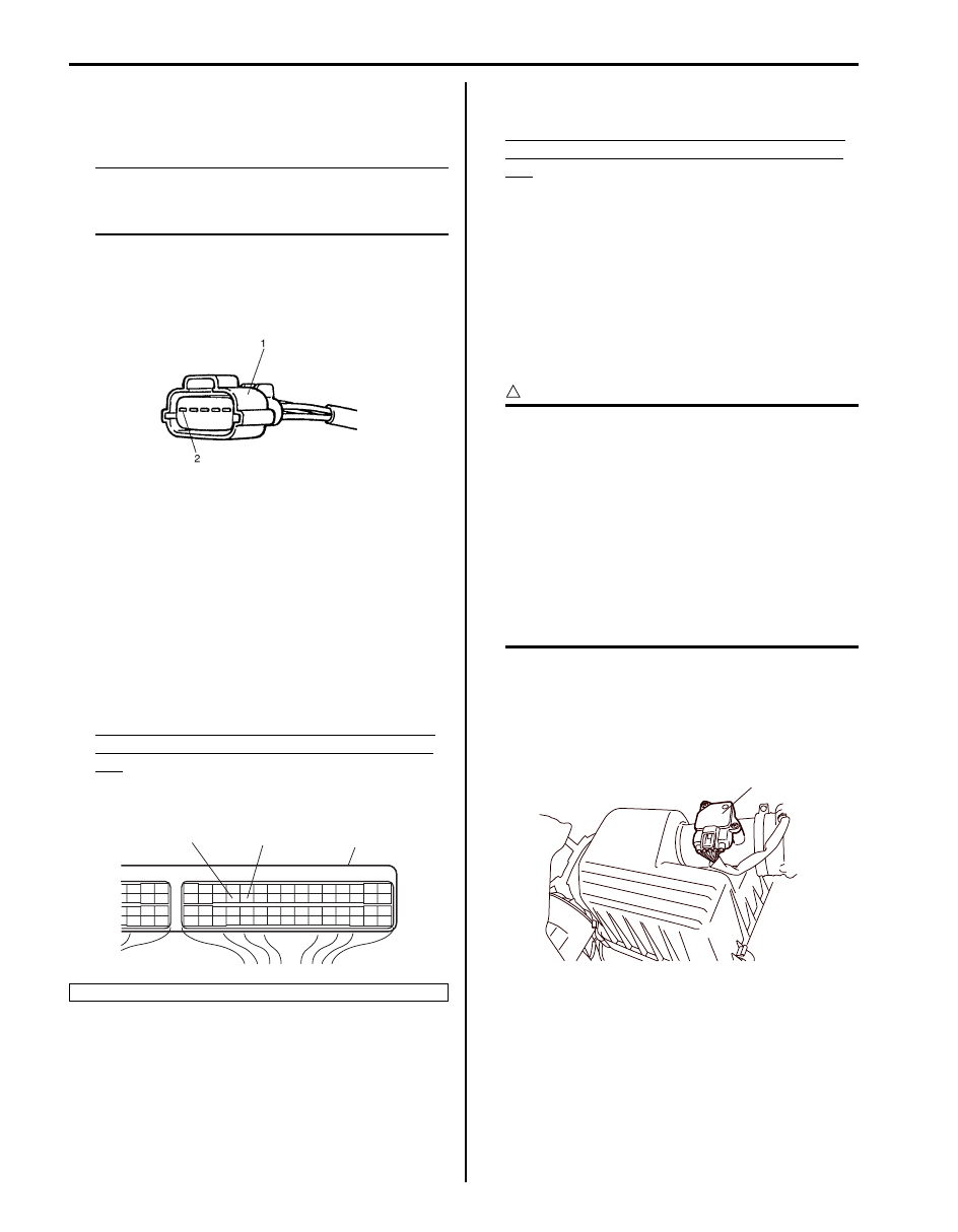
1) Disconnect MAF and IAT sensor connector.
2) Connect voltmeter to “BLU/BLK” wire terminal (2) of
MAF and IAT sensor connector (1) disconnected and
ground.
3) Turn ON ignition switch and check that voltage is
battery voltage.
If not, check if wire harness is open or connection is
poor.
4) Turn OFF ignition switch and connect connector to
MAF and IAT sensor.
5) Connect special tool between ECM and ECM
connector referring to “Inspection of ECM and Its
Circuits in Section 1A”
6) Turn ON ignition switch and check MAF signal
voltage between “C37-26” terminal circuit and “C37-
27” terminal circuit of special tool.
MAF signal voltage between “C37-26” terminal
circuit and “C37-27” terminal circuit of special
tool
MAF signal voltage of MAF and IAT sensor with
ignition switch turned ON: 0.5 – 1.0 V
7) Start engine and check that voltage is lower than 5 V
and it rises as engine speed increases.
MAF signal voltage between “C37-26” terminal
circuit and “C37-27” terminal circuit of special
tool
MAF signal reference voltage of MAF and IAT
sensor at specified Idle speed: 1.3 – 1.8 V
8) If check result is not as specified above, cause may
lie in wire harness, connector connection, MAF and
IAT sensor or ECM.
Mass Air Flow (MAF) and Intake Air
Temperature (IAT) Sensor Removal and
Installation
S5JB0A1306020
CAUTION
!
• Do not disassemble MAF and IAT sensor.
• Do not expose MAF and IAT sensor to any
shock.
• Do not clean MAF and IAT sensor.
• If MAF and IAT sensor has been dropped, it
should be replaced.
• Do not blow compressed air by using air
gun or the like.
• Do not put finger or any other object into
MAF and IAT sensor. Malfunction may
occur.
Removal
1) Disconnect negative cable at battery.
2) Disconnect MAF and IAT sensor connector.
3) Remove MAF and IAT sensor (1) from air cleaner
case.
1. ECM
I3RB0A130009-01
“C37-27”
“C37-26”
1
I4RS0A130009-01
1
I5JB0A130033-02
Engine Electrical Devices: 1C-14
Installation
Reverse removal procedure noting the followings.
• Tighten MAF and IAT sensor screws to specified
torque.
Tightening torque
MAF and IAT sensor screw (a): 1.5 N·m (0.15 kgf-
m, 1.1 lb-ft)
• Connect MAF and IAT sensor connector securely.
Mass Air Flow (MAF) and Intake Air
Temperature (IAT) Sensor Inspection
S5JB0A1306021
CAUTION
!
Do not heat up MAF and IAT sensor more
than 100
°C (212 °F). Otherwise, MAF and IAT
sensor will be damaged.
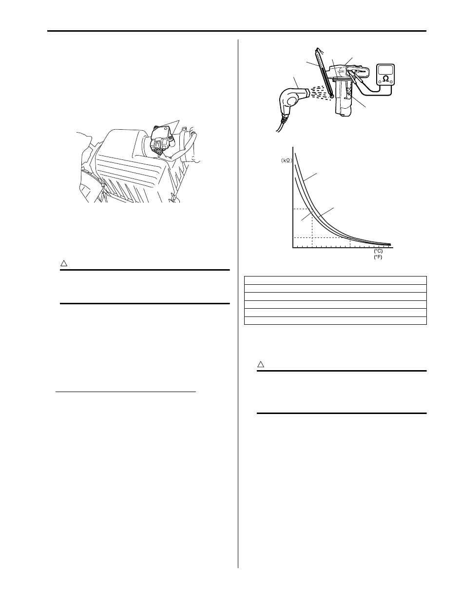
• Check sensor O-ring (1) for damage and
deterioration. Replace as necessary.
• Blow hot air to temperature sensing part (2) of MAF
and IAT sensor (3) using hot air drier (4) and measure
resistance between sensor terminals while heating air
gradually.
If measured resistance does not show such
characteristic as shown, replace MAF and IAT sensor.
Intake air temperature sensor resistance
–20
°C (–4 °F): 13.6 – 18.4 kΩ
20
°C (68 °F): 2.21 – 2.69 kΩ
60
°C (140 °F): 0.493 – 0.667 kΩ
Vacuum Tank Assembly Inspection (For J20
Engine)
S5JB0A1306030
CAUTION
!
Do not apply vacuum more than –86 kPa (–
12.47 psi); otherwise intake manifold tuning
vacuum solenoid valve and vacuum tank
could be damaged.
Intake manifold tuning vacuum solenoid valve
1) With ignition switch OFF, disconnect connector from
vacuum solenoid valve.
(a)
I5JB0A130034-02
[A]: Lower limit
[B]: Nominal
[C]: Upper limit
[D]: Resistance
[E]: Temperature
5. Temperature gauge
20
0
68
32
104
140
176
40
60
80
(2.45)
(0.58)
1
2
3
4
5
[A]
[B]
[E]
[C]
[D]
I4RS0A130012-01
1C-15 Engine Electrical Devices:
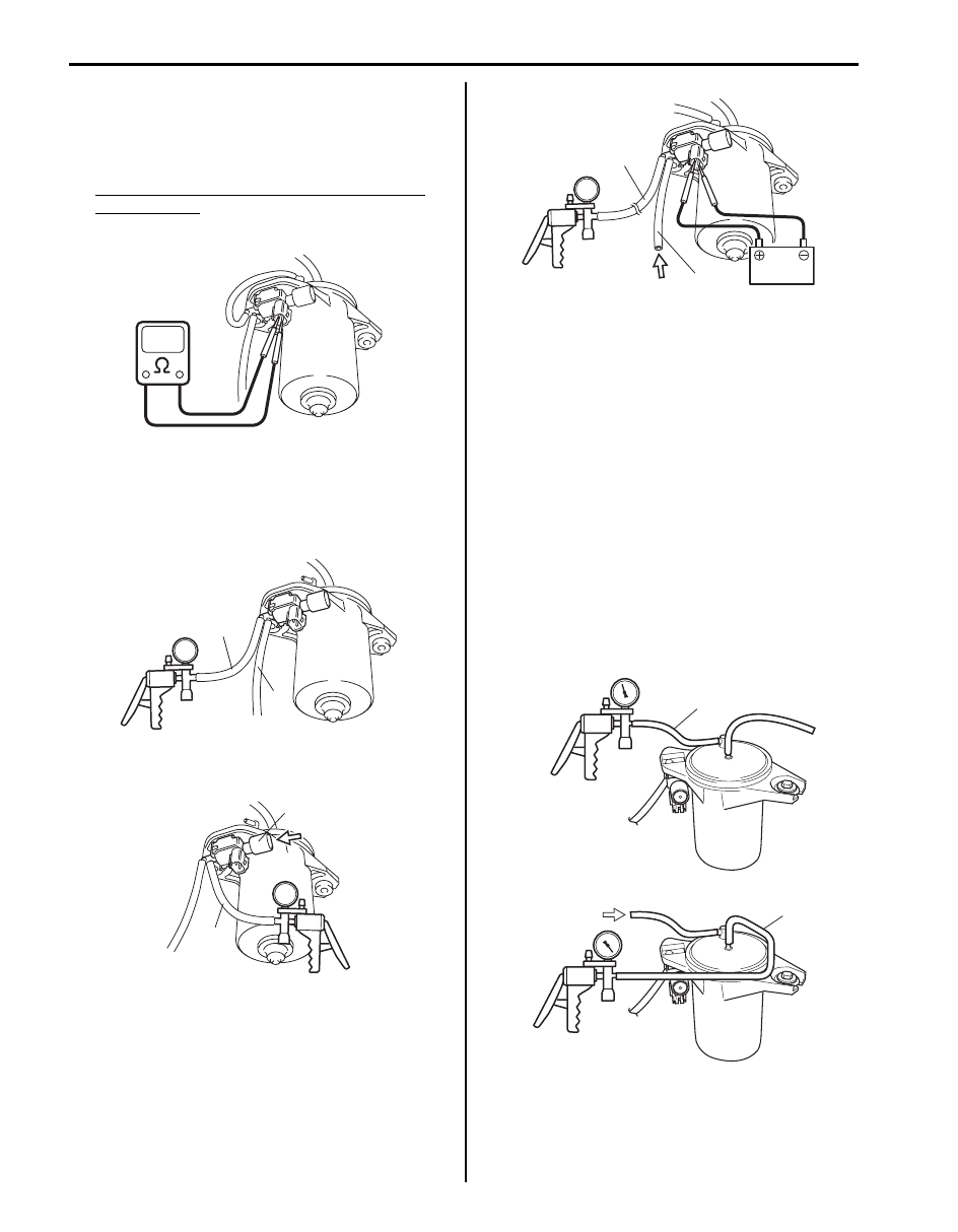
2) Check resistance of intake manifold tuning vacuum
solenoid valve.
If resistance is as specified, proceed to next
operation check. If not, replace intake manifold
tuning vacuum solenoid valve.
Resistance of intake manifold tuning vacuum
solenoid valve
Between two terminals: 33 – 39
Ω at 20 °C (68 °F)
3) Disconnect vacuum hoses (1 and 2) from intake
manifold tuning valve and vacuum tank.
4) With connector disconnected, apply vacuum (–53
kPa (– 7.69 psi) to –67 kPa (–9.72 psi)) to hose (2).
Vacuum is maintained.
5) With connector disconnected, apply vacuum to hose
(1). Air goes into nozzle (2).
6) Connect 12 V-battery to intake manifold tuning
vacuum solenoid valve terminals. In this state, apply
vacuum to hose (2). Air goes into hose (1).
If check result is not as described, replace intake
manifold tuning vacuum solenoid valve.
7) Connect vacuum hoses to intake manifold tuning
valve and vacuum tank.
8) Connect intake manifold tuning vacuum solenoid
valve connector securely.
Vacuum Tank
1) Check outside of vacuum tank for damage visually.
2) Disconnect vacuum hoses from intake manifold and
intake manifold tuning vacuum solenoid valve.
3) Check vacuum passage of vacuum tank for clog and
leakage as follows by using vacuum pump.
a) When applying vacuum (– 53 kPa (– 7.69 psi) to
– 67 kPa (–9.72 psi)) to hose (1), vacuum is
maintained (there is no leakage): [A]
b) When applying vacuum to hose (2), vacuum is
not maintained: [B]
If check result is not described, replace vacuum
tank assembly.
4) Connect vacuum hoses to intake manifold and intake
manifold tuning vacuum solenoid valve.
I5JB0A130005-01
1
2
I5JB0A130006-01
2
1
I5JB0A130007-01
2
1
I5JB0A130008-01
[B]
2
[A]
1
I5JB0A130009-01

Engine Electrical Devices: 1C-16
Electric Load Current Sensor On-Vehicle
Inspection (For J20 Engine)
S5JB0A1306031
Using SUZUKI Scan Tool
1) Connect scan tool to DLC with ignition switch turned
OFF.
2) Check “Battery Current” displayed on scan tool at
following condition.
Battery current
Ignition switch ON: 5.0 – 6.0 A
Run engine at 2000 rpm, headlight ON: 19.0 – 23.0 A
Run engine at 2000 rpm, headlight ON and blower
motor switch is HI position: 37.0 – 42.0 A
If check result is satisfactory, electric load current sensor
is in good condition.
If check result is not satisfactory, check the following
parts and circuit.
• Electric load current sensor circuit (power, ground and
output)
• Following charging system components
– Battery (refer to “Battery Inspection in Section 1J”)
– Generator (refer to “Generator Inspection in
– Generator output control circuit (refer to “Generator
Test (Undercharged Battery Check) in Section 1J”)
– Generator field coil monitor circuit (refer to
“Generator Inspection in Section 1J”)
If electric load current sensor circuit and charging
system is in good condition, electric load current sensor
is faulty.
Without Using SUZUKI Scan Tool
1) Measure sensor voltage between “C37-9” terminal of
ECM connector and vehicle body ground referring to
“Inspection of ECM and Its Circuits in Section 1A”.
If check result is satisfactory, electric load current
sensor is in good condition.
If check result is not satisfactory, check the following
parts and circuit.
• Electric load current sensor circuit (power, ground
and output)
• Following charging system components
– Battery (refer to “Battery Inspection in Section
– Generator (refer to “Generator Inspection in
– Generator output control circuit (refer to
“Generator Test (Undercharged Battery Check)
in Section 1J”)
– Generator field coil monitor circuit (refer to
“Generator Inspection in Section 1J”)
If electric load current sensor circuit and charging
system is in good condition, electric load current
sensor is faulty.
Electric Load Current Sensor Removal and
Installation (For J20 Engine)
S5JB0A1306032
Removal
1) Remove battery from vehicle referring to “Battery
Dismounting and Remounting in Section 1J”.
2) Detach fuse box No.1 (1) from its bracket.
3) Remove fuse block cover.
4) Disconnect connector from electric load current
sensor.
5) Remove electric load current sensor (1) from fuse
box No.1 (2).
Installation
Reverse removal procedure noting the following.
• Install battery referring to “Battery Dismounting and
1
I5JB0A130010-02
1
2
I5JB0A130011-01
Нет комментариевНе стесняйтесь поделиться с нами вашим ценным мнением.
Текст