Suzuki Grand Vitara JB416 / JB420. Manual — part 80
1C-5 Engine Electrical Devices:
Accelerator Pedal Position (APP) Sensor
Assembly On-Vehicle Inspection
S5JB0A1306024
1) Check that accelerator pedal position (APP) sensor
assembly has been mounted to vehicle body
properly (no pinched floor carpet, etc).
If mounting is not properly, reinstall accelerator pedal
position (APP) sensor assembly properly referring to
“Accelerator Pedal Position (APP) Sensor Assembly
Removal and Installation”.
2) Connect scan tool to DLC with ignition switch turned
OFF.
3) Turn ON ignition switch and select “Data List” mode
on scan tool.
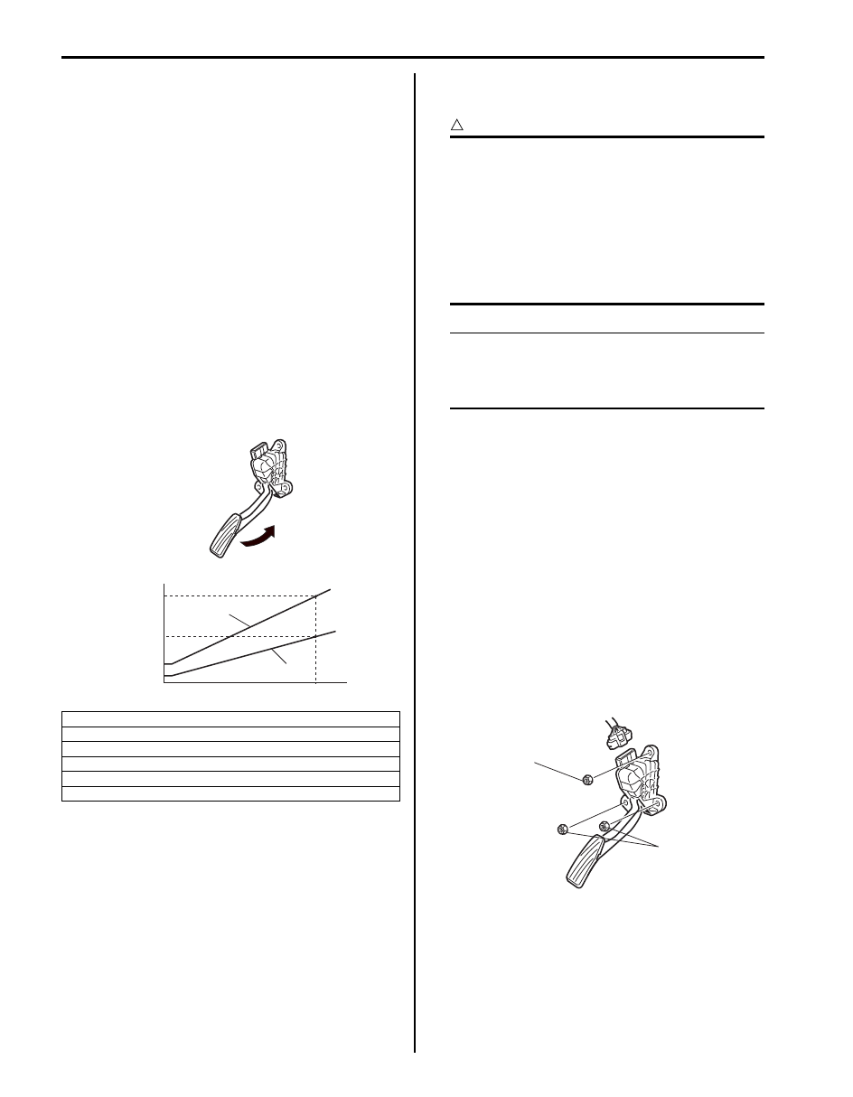
4) Check that accelerator pedal position sensor voltage
varies as the following graph.
If sensor voltage is out of specified value or does not
vary linearly as the following graph, check
accelerator pedal position (APP) sensor assembly
referring to “Accelerator Pedal Position (APP)
Sensor Assembly Inspection”.
Accelerator Pedal Position (APP) Sensor
Assembly Removal and Installation
S5JB0A1306027
CAUTION
!
• Do not expose accelerator pedal position
(APP) sensor assembly to excessive shock
like a dropping it. If accelerator pedal
position (APP) sensor assembly has been
exposed to excessive shock, it should be
replaced.
• Be careful not to expose sensor section of
accelerator pedal position (APP) sensor
assembly to water.
NOTE
After replacing accelerator pedal position
(APP) sensor assembly, perform calibration
of throttle valve referring to “Electric Throttle
Body System Calibration”.
Removal
1) Disconnect negative cable at battery.
2) Disconnect connector from accelerator pedal
position (APP) sensor assembly.
3) Remove accelerator pedal position (APP) sensor
assembly from its bracket.
Installation
Reverse removal procedure for installation noting the
following.
• Tighten accelerator pedal position (APP) sensor
assembly upper nut (1) first and then lower nuts (2) to
specified torque.
Tightening torque
Accelerator pedal position (APP) sensor assembly
nut (a): 6.0 N·m (0.6 kgf-m, 4.5 lb-ft)
• If APP sensor assembly bracket is removed, tighten
its mounting nuts to specified torque
Tightening torque
APP sensor assembly bracket nut: 6.0 N·m (0.6
kgf-m, 4.3 lb-ft)
• Connect connector to accelerator pedal position
(APP) sensor assembly securely.
[A]: Accelerator pedal position (APP) sensor (main) voltage
[B]: Accelerator pedal position (APP) sensor (sub) voltage
[C]: Sensor output voltage
[D]: Idle position of accelerator pedal
[E]: Full depressed position of accelerator pedal
[F]: Pedal stroke
[C]
[B]
[D]
[F]
[E]
[A]
1.74 - 2.17 V
0.65 - 0.82 V
3.50 - 4.27 V
0.30 - 0.44 V
I5JB0A130018-05
1, (a)
2, (a)
I5JB0A130036-01
Engine Electrical Devices: 1C-6
Accelerator Pedal Position (APP) Sensor
Assembly Inspection
S5JB0A1306026
Check accelerator pedal position (APP) sensor (main
and sub) output voltage as following steps.
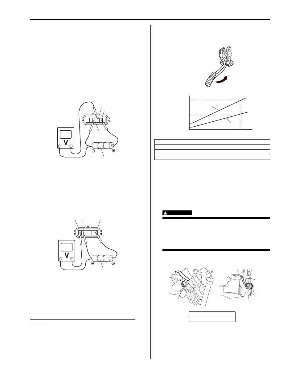
1) For accelerator pedal position (APP) sensor (main),
arrange 3 new 1.5 V batteries (1) in series (check
that total voltage is 4.7 – 5.0 V) and connect its
positive terminal to “Vin 1” terminal (2) and negative
terminal to “Ground 1” terminal (3) of sensor. Then
using voltmeter, connect positive terminal to “Vout 1”
terminal (4) of sensor and negative terminal to
battery.
2) For accelerator pedal position (APP) sensor (sub),
arrange 3 new 1.5 V batteries (1) in series (check
that total voltage is 4.7 – 5.0 V) and connect its
positive terminal to “Vin 2” terminal (2) and negative
terminal to “Ground 2” terminal (3) of sensor. Then
using voltmeter, connect positive terminal to “Vout 2”
terminal (4) of sensor and negative terminal to
battery.
3) Measure output voltage variation while accelerator
pedal is no depressed and fully depressed as
following specification.
If sensor voltage is out of specified value or does not
vary linearly as the following graph, replace accelerator
pedal position (APP) sensor assembly.
Accelerator pedal position (APP) sensor output
voltage
Accelerator pedal position (APP) sensor (main)
output voltage [A]: 0.82 – 3.50 V, varying according
to depressed extent of accelerator pedal
Accelerator pedal position (APP) sensor (sub)
output voltage [B]: 0.44 – 1.74 V, varying according
to depressed extent of accelerator pedal
Engine Coolant Temperature (ECT) Sensor
Removal and Installation
S5JB0A1306008
Removal
1) Disconnect negative cable at battery.
2) Drain coolant referring to “Cooling System Draining
WARNING
!
To avoid danger of being burned, do not
remove radiator cap while engine and
radiator are still hot.
Scalding fluid and steam can be blown out
under pressure if cap is taken off too soon.
3) Disconnect connector from ECT sensor (1).
4) Remove ECT sensor from water outlet cap.
1
2
3
4
I5JB0A130019-02
1
2
3
4
I5JB0A130020-02
[C]: Sensor output voltage
[D]: Idle position of accelerator pedal
[E]: Fully depressed position of accelerator pedal
[F]: Pedal stroke
[A]: For J20 engine
[B]: For M16 engine
[C]
[B]
[D]
[F]
[E]
[A]
1.74 - 2.17 V
0.65 - 0.82 V
3.50 - 4.27 V
0.30 - 0.44 V
I5JB0A130021-05
[B]
[A]
1
1
I5JB0A130022-03
1C-7 Engine Electrical Devices:
Installation
Reverse removal procedure noting the following.
• Clean mating surfaces of ECT sensor and water outlet
cap.
• Check O-ring for damage and replace, if necessary.
• Tighten ECT sensor (1) to specified torque.
Tightening torque
ECT sensor (a): 12.5 N·m (1.25 kgf-m, 9.0 lb-ft)
• Connect connector to ECT sensor securely.
• Refill coolant referring to “Cooling System Flush and
Engine Coolant Temperature (ECT) Sensor
Inspection
S5JB0A1306009
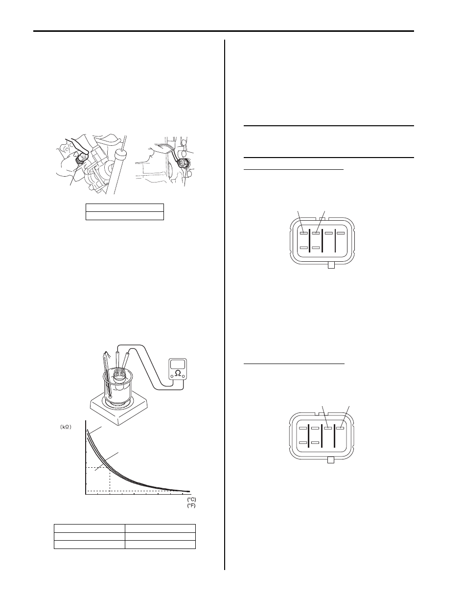
Immerse temperature sensing part of ECT sensor in
water (or ice) and measure resistance between sensor
terminals while heating water gradually.
If measured resistance doesn’t show such characteristic
as shown, replace ECT sensor.
Air Fuel Ratio (A/F) Sensor On-Vehicle
Inspection
S5JB0A1306028
Heater
1) Disconnect A/F sensor connector.
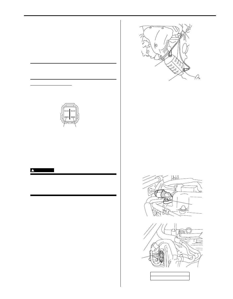
2) Using ohmmeter, measure resistance of Sensor
heater between terminals “V
B
” and “GND” at sensor
connector. If found faulty, replace A/F sensor.
NOTE
Temperature of sensor affects resistance
value largely. Make sure that sensor heater is
at correct temperature.
A/F sensor heater resistance
2 – 3
Ω at 20 °C (68 °F)
Viewed from terminal side
3) Connect A/F sensor connector securely.
Adjusting Resistor
1) Disconnect A/F sensor connector.
2) Using ohmmeter, measure resistance of adjusting
resistor between terminals “R+” and “R–” at A/F
sensor connector.
If found faulty, replace A/F sensor.
Adjusting resistor resistance
100 – 58000
Ω at 20 °C (68 °F)
Viewed from terminal side
3) Connect A/F sensor connector securely.
[A]: For J20 engine
[B]: For M16 engine
[A]: Lower limit
[D]: Resistance
[B]: Normal
[E]: Temperature
[C]: Upper limit
[B]
[A]
1, (a)
1, (a)
I5JB0A130023-02
20
0
68
32
104
140
176
40
60
80
[E]
2.29 - 2.62
0.309 - 0.331
[A]
[B]
[C]
[D]
I5JB0A130037-01
“GND”
“V
B
”
I5JB0A130001-02
“R+”
“R
−
”
I5JB0A130002-02
Engine Electrical Devices: 1C-8
Heated Oxygen Sensor (HO2S-2) Heater On-
Vehicle Inspection
S5JB0A1306010
1) Disconnect sensor connector.
2) Using ohmmeter, measure resistance of sensor
heater between terminals “V
B
” and “GND” at sensor
connector.
If found faulty, replace oxygen sensor.
NOTE
Temperature of sensor affects resistance
value largely. Make sure that sensor heater is
at correct temperature.
HO2S heater resistance
5.0 – 6.4
Ω at 20 °C (68 °F)
Viewed from terminal side
3) Connect sensor connector securely.
Air Fuel Ratio (A/F) Sensor, Heated Oxygen
Sensor (HO2S-2) Removal and Installation
S5JB0A1306011
Removal
WARNING
!
To avoid danger of being burned, do not
touch exhaust system when system is hot. A/
F sensor and/or oxygen sensor removal
should be performed when system is cool.
1) Disconnect negative cable at battery.
2) Disconnect connector of A/F sensor and/or heated
oxygen sensor.
3) Remove A/F sensor (1) and/or heated oxygen
sensor (2) from exhaust No.1 pipe.
Installation
Reverse removal procedure noting the following.
• Tighten A/F sensor (1) to specified torque.
Tightening torque
A/F sensor (a): 45 N·m (4.5 kgf-m, 32.5 lb-ft)
• Tighten heated oxygen sensor (2) to specified torque.
Tightening torque
Heated oxygen sensor (b): 45 N·m (4.5 kgf-m,
32.5 lb-ft)
Camshaft Position (CMP) Sensor Removal and
Installation
S5JB0A1306013
Removal
1) Disconnect negative cable at battery.
2) Disconnect connector from CMP sensor.
3) Remove camshaft position sensor from cylinder
head cover (for J20 engine) or cylinder head (for
M16 engine).
Installation
1) Install camshaft position sensor to cylinder head
cover (for J20 engine) or cylinder head (for M16
engine).
Tightening torque
CMP sensor bolt (a): 11 N·m (1.1 kgf-m, 8.0 lb-ft)
“GND”
“V
B
”
I5JB0A130024-03
[A]: For J20 engine
[B]: For M16 engine
1,(a)
2,(b)
I5JB0A130025-02
(a)
[B]
[A]
(a)
I5JB0A130026-03
Нет комментариевНе стесняйтесь поделиться с нами вашим ценным мнением.
Текст