Suzuki Grand Vitara JB416 / JB420. Manual — part 81
1C-9 Engine Electrical Devices:
2) Connect connector to CMP sensor securely.
3) Connect negative cable to battery.
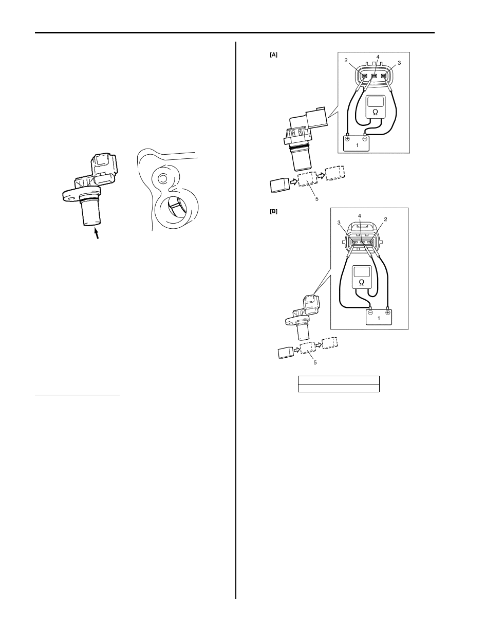
Camshaft Position (CMP) Sensor Inspection
S5JB0A1306012
Visual check
• Check that O-ring is free from damage.
• Check that end face of sensor and signal rotor tooth
are free from any metal particles and damage.
Performance check
1) Remove metal particles on end face of CMP sensor,
if any.
2) Arrange 12 V battery (1) and connect its positive
terminal to “Vin” terminal (2) and negative terminal to
“Ground” terminal (3) of sensor. Then using
ohmmeter, measure resistance between “Vout”
terminal (4) of sensor and negative terminal of
battery by passing magnetic substance (iron) (5)
while keeping approximately 1 mm (0.03 in.) gap
with respect to end face of CMP sensor.
If resistance does not vary as specified below,
replace CMP sensor.
CMP sensor resistance
Resistance varies from less than 220
Ω (ON) to
infinity (OFF) or from infinity (OFF) to less than 220
Ω (ON)
Crankshaft Position (CKP) Sensor Removal and
Installation
S5JB0A1306015
For J20 Engine
Removal
1) Remove transmission assembly from vehicle
referring to “Automatic Transmission Assembly
Dismounting and Remounting in Section 5A” or
“Manual Transmission Assembly Dismounting and
Remounting in Section 5B”.
2) Remove drive plate or flywheel from crankshaft.
3) Disconnect connector from crankshaft position
sensor.
4) Remove crankshaft position sensor (1) from cylinder
block (2).
I4RS0B130015-01
[A]: For J20 engine
[B]: For M16 engine
I5JB0A130027-01

Engine Electrical Devices: 1C-10
Installation
Reverse removal procedure noting the following.
• Apply engine oil to O-ring of sensor.
• Tighten CKP sensor bolt to specified torque.
Tightening torque
CKP sensor bolt (a): 11 N·m (1.1 kgf-m, 8.0 lb-ft)
• Connect connector and fix wire harness with clamp
securely.
For M16 Engine
Removal
1) Disconnect negative cable at battery.
2) Remove generator drive belt, loosen pivot bolt and
move generator outward.
3) Disconnect connector from crankshaft position
sensor.
4) Remove crankshaft position sensor (1) from cylinder
block.
Installation
1) Install crankshaft position sensor to cylinder block.
Tighten CKP sensor bolt to specified torque.
Tightening torque
CKP sensor bolt (a): 10 N·m (1.0 kgf-m, 7.5 lb-ft)
2) Connect connector to CKP sensor securely.
3) Adjust generator drive belt tension referring to
4) Connect negative cable to battery.
Crankshaft Position (CKP) Sensor Inspection
S5JB0A1306014
For J20 Engine
Waveform Check
Using oscilloscope, check that CKP sensor signal is
outputted properly referring to “Reference waveform
No.20” and “Reference waveform No.21” of “Inspection
of ECM and Its Circuits in Section 1A”.
If sensor signal is outputted properly, CKP sensor is in
good condition.
Visual check
• Check that O-ring is free from damage.
• Check that end face of sensor and signal plate tooth
are free from any metal particles and damage.
I2RH01130021-01
I2RH0B130012-01
(a)
I5JB0A130028-01
I5JB0A130003-01
1C-11 Engine Electrical Devices:
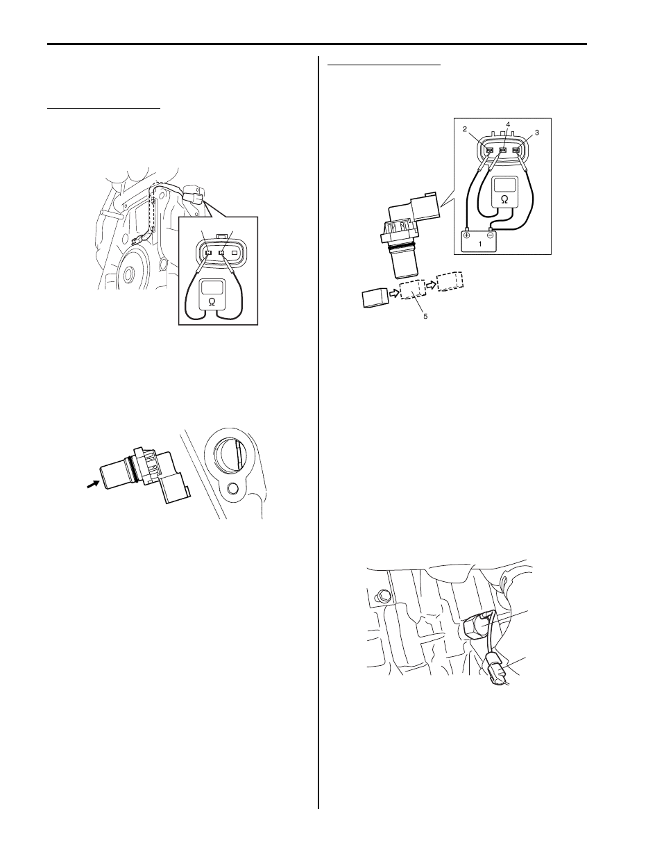
Resistance check
Measure resistance between “1” and “2” terminals of
CKP sensor.
CKP sensor resistance
480 – 660
Ω at 20 °C, 68 °F
If measured resistance is out of specified value, replace
CKP sensor.
For M16 Engine
Visual check
• Check that O-ring is free from damage.
• Check that end face of sensor and signal pulley tooth
are free from any metal particles and damage.
Performance check
1) Remove metal particles on end face of CKP sensor,
if any.
2) Arrange 12 V battery (1) and connect its positive
terminal to “Vin” terminal (2) and negative terminal to
“Ground” terminal (3) of sensor. Then using
ohmmeter, measure resistance between “Vout”
terminal (4) of sensor and negative terminal of
battery by passing magnetic substance (iron) (5)
while keeping approximately 1 mm (0.03 in.) gap
with respect to end face of CKP sensor.
If resistance does not vary as specified below,
replace CKP sensor.
CKP sensor resistance
Resistance varies from less than 220
Ω (ON) to
infinity (OFF) or from infinity (OFF) to less than 220
Ω (ON)
Knock Sensor Removal and Installation
S5JB0A1306017
Removal
1) Disconnect negative cable at battery.
2) Hoist vehicle.
3) For M16 engine, remove starting motor referring to
“Starting Motor Dismounting and Remounting in
Section 1I”.
4) Disconnect knock sensor connector (1).
5) Remove knock sensor (2) from cylinder block.
Installation
Reverse removal procedure for installation.
Tightening torque
Knock sensor (a): 22 N·m (2.2 kgf-m, 16.0 lb-ft)
1
2
I5JB0A130004-01
I3RB0A130006-01
I4RS0B130017-01
2, (a)
1
I5JB0A130029-02
Engine Electrical Devices: 1C-12
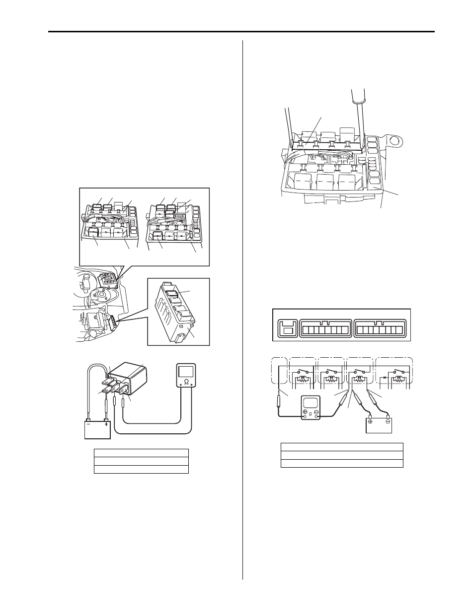
Control Relay Inspection
S5JB0A1306018
Control Relay
1) Disconnect negative cable at battery.
2) Remove main relay (1), fuel pump relay (3), starting
motor control relay (2), throttle actuator control relay
(4) and HO2S heater relay (5) (for M16 engine) from
fuse box No.2 (6) and/or relay box (7).
3) Check that there is no continuity between terminal
“C” and “D”. If there is continuity, replace relay.
4) Connect battery positive (+) terminal to terminal “B”
of relay. Connect battery negative (–) terminal to
terminal “A” of relay. Check for continuity between
terminal “C” and “D”. If there is no continuity when
relay is connected to the battery, replace relay.
Integration Relay No.2 (For J20 Engine)
1) Disconnect negative cable at battery.
2) Remove included in integration relay No.2 (1) from
fuse box No.2 (2).
3) Check that there is no continuity between terminals
“E41-1” and “E37-8” of relay.
If there is continuity, replace relay.
4) Connect battery positive (+) terminal to “E37-7”
terminal of relay. Connect battery negative (–)
terminal to “E37-6” terminal of relay. Check for
continuity between terminal “E41-1” and “E37-8”. If
there is no continuity when relay is connected to the
battery, replace integration relay No.2.
[A]: For J20 engine
[B]: For M16 engine
8. Integration relay No.2
"D"
"B"
"A"
"C"
[A]
[B]
3
1
8
3
1
5
2
2
6
6
4
7
I5JB0A130030-02
[A]: A/T relay
[B]: HO2S heater relay
[C]: Compressor relay
2
1
I5JB0A130031-02
1
1
2
3
4
5
6
7
8
1
2
3
4
5
6
7
8
E41
E41
E41
E37
E38
“E37-6”
[A]
[B]
[C]
“E41-1”
“E37-8”
“E37-7”
I5JB0A130032-02
Нет комментариевНе стесняйтесь поделиться с нами вашим ценным мнением.
Текст