Suzuki Grand Vitara JB416 / JB420. Manual — part 20
1A-29 Engine General Information and Diagnosis:
Step 2: DTC / Freeze Frame Data Check, Record and
Clearance
First, check DTC (including pending DTC), referring to
“DTC Check”. If DTC is indicated, print it and freeze
frame data or write them down and then clear them by
referring to “DTC Clearance”. DTC indicates malfunction
that occurred in the system but does not indicate
whether it exists now or it occurred in the past and the
normal condition has been restored now. To check which
case applies, check the symptom in question according
to Step 5 and recheck DTC according to Step 6 and 7.
Attempt to diagnose a trouble based on DTC in this step
only or failure to clear the DTC in this step will lead to
incorrect diagnosis, trouble diagnosis of a normal circuit
or difficulty in troubleshooting.
Step 3 and 4: Visual Inspection
As a preliminary step, be sure to perform visual check of
the items that support proper function of the engine
referring to “Visual Inspection”.
Step 5: Trouble Symptom Confirmation
Based on information obtained in “Step 1: Customer
Complaint Analysis: ” and “Step 2: DTC / Freeze Frame
Data Check, Record and Clearance: ”, confirm trouble
symptoms. Also, reconfirm DTC according to “DTC
Confirmation Procedure” described in each DTC diag.
flow.
Step 6 and 7: Rechecking and Record of DTC /
Freeze Frame Data
Refer to “DTC Check” for checking procedure.
Step 8: Engine Basic Inspection and Engine
Symptom Diagnosis
Perform basic engine check according to “Engine Basic
Inspection” first. When the end of the flow has been
reached, check the parts of the system suspected as a
possible cause referring to “Engine Symptom Diagnosis”
and based on symptoms appearing on the vehicle
(symptoms obtained through steps of customer
complaint analysis, trouble symptom confirmation and/or
basic engine check) and repair or replace faulty parts, if
any.
Step 9: Troubleshooting for DTC (See each DTC
Diag. Flow)
Based on the DTC indicated in Step 6 or 7 and referring
to the applicable DTC diag. flow, locate the cause of the
trouble, namely in a sensor, switch, wire harness,
connector, actuator, ECM or other part and repair or
replace faulty parts.
Step 10: Intermittent Problems Check
Check parts where an intermittent trouble is easy to
occur (e.g., wire harness, connector, etc.), referring to
“Intermittent and Poor Connection Inspection in Section
00” and related circuit of DTC recorded in Step 2.
Step 11: Final Confirmation Test
Confirm that the problem symptom has gone and the
engine is free from any abnormal conditions. If what has
been repaired is related to the DTC, clear the DTC once,
perform DTC confirmation procedure and confirm that no
DTC is indicated.
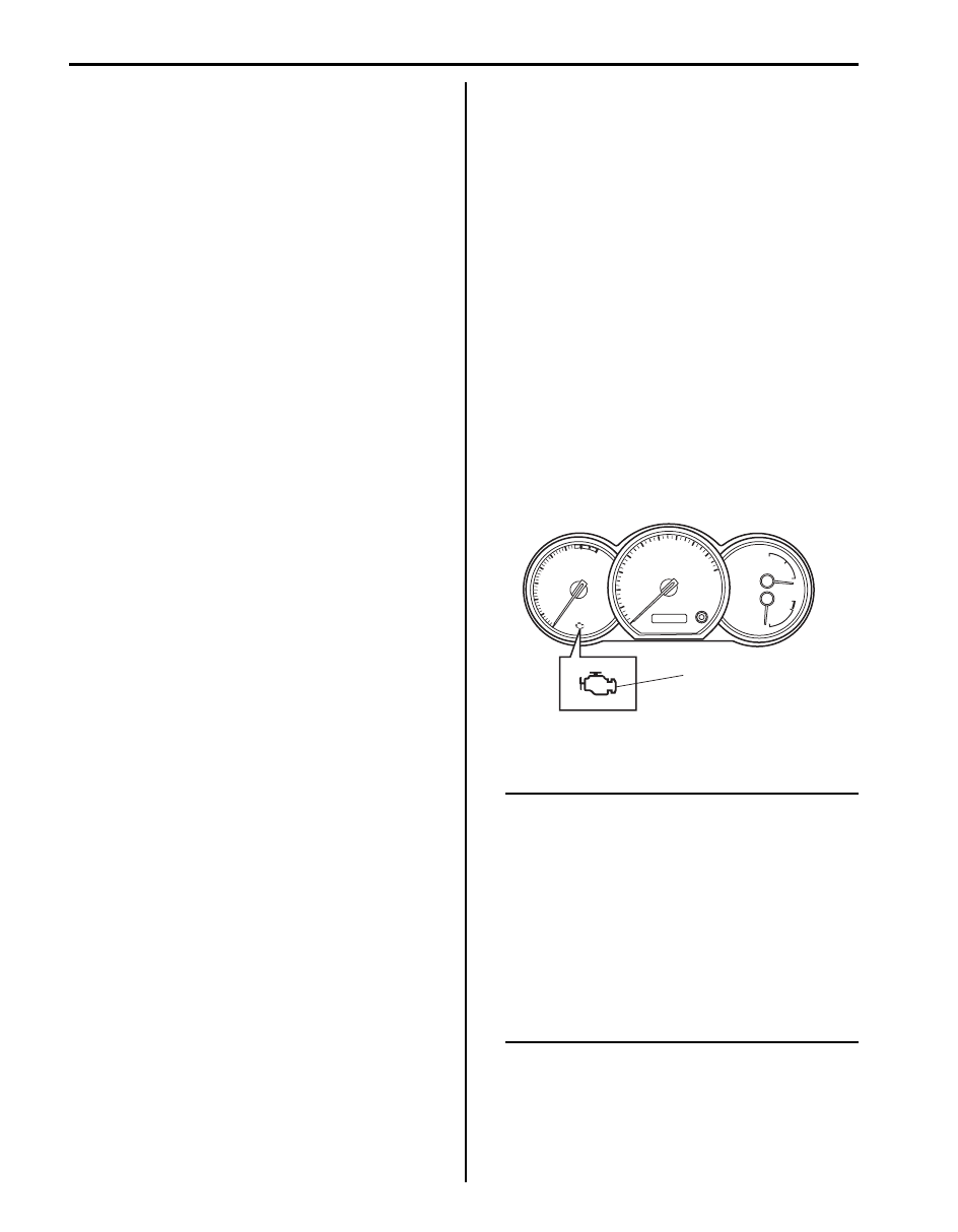
Malfunction Indicator Lamp (MIL) Check
S5JB0A1104002
1) Turn ON ignition switch (with engine at stop) and
check that MIL (1) lights.
If MIL does not light up (or MIL dims) but engine can
be starting, go to “Malfunction Indicator Lamp Does
Not Come ON with Ignition Switch ON and Engine
Stop (but Engine Can Be Started)” for
troubleshooting.
If MIL does not light with ignition switch ON and
engine does not start though it is cranked up, go to
“ECM Power and Ground Circuit Check”.
2) Start engine and check that MIL turns OFF.
If MIL remains ON and no DTC is stored in ECM, go
to “Malfunction Indicator Lamp Remains ON after
Engine Starts” for troubleshooting.
DTC Check
S5JB0A1104003
NOTE
The MIL is turned on when the ECM and/or
TCM detect malfunction(s). Each ECM and
TCM stores diagnostic information as the
diagnostic trouble code (DTC) in its memory
and outputs the DTC to the scan tool.
Therefore, check both of the ECM and TCM
for any DTC with the scan tool because the
DTC stored in ECM and TCM is not read and
displayed at a time. However, each of the
ECM and TCM needs not to be checked with
the generic scan tool because the DTC stored
in ECM and TCM is read and displayed at a
time.
1
I5JB0A110018-01
Engine General Information and Diagnosis: 1A-30
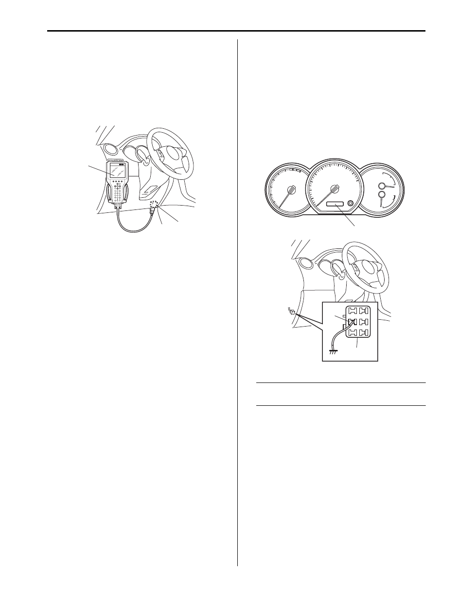
Using Scan Tool
1) Prepare SUZUKI scan tool or OBD generic scan tool
(vehicle not equipped with diagnosis connector).
2) With ignition switch turned OFF, connect it to data
link connector (DLC) (1) located on underside of
instrument panel at driver’s seat side.
Special tool
(A): SUZUKI scan tool
3) Turn ignition switch ON and confirm that MIL lights.
4) Read DTC, pending DTC and freeze frame data
according to instructions displayed on scan tool and
print them or write them down. Refer to scan tool
operator’s manual for further details.
If communication between scan tool and ECM is not
possible, check if scan tool is communicable by
connecting it to ECM in another vehicle. If
communication is possible in this case, scan tool is
in good condition. Then check data link connector
and serial data line (circuit) in the vehicle with which
communication was not possible. If connector and
circuit are OK, check that power supply and ground
circuits of ECM and DLC are in good condition
referring to “ECM Power and Ground Circuit Check”.
5) After completing the check, turn ignition switch OFF
and disconnect scan tool from data link connector.
Without Using Scan Tool (Vehicle Equipped with
Diagnosis Connector)
1) Turn ignition switch to OFF position.
2) Using service wire, ground diagnosis switch terminal
(1) of diagnosis connector (2).
3) Turn ON ignition switch and check DTC displayed on
odometer (3) of combination meter.
When more than 2 DTCs are stored in memory,
blinking for each DTC starts with the smallest DTC
number in increasing order. Also, DTC is indicated
repeatedly until the ignition switch is turned OFF or
disconnect service wire.
NOTE
When no DTC is detected, display on
odometer of combination meter is “0000”.
4) After completing the check, turn ignition switch to
OFF position and disconnect service wire from
diagnosis connector.
DTC Clearance
S5JB0A1104004
Using Scan Tool
1) Connect OBD generic scan tool or SUZUKI scan tool
to data link connector in the same manner as when
making this connection for DTC check.
2) Turn ignition switch OFF and then ON.
3) Erase DTC and pending DTC according to
instructions displayed on scan tool. Refer to scan
tool operator’s manual for further details.
4) After completing the clearance, turn ignition switch
OFF and disconnect scan tool from data link
connector.
(A)
1
I5JB0A110019-01
3
2
1
I5JB0A110020-01
1A-31 Engine General Information and Diagnosis:
NOTE
DTC and freeze frame data stored in ECM
memory are also cleared in the following
cases. Be careful not to clear them before
keeping their record.
• When power to ECM is cut off (by
disconnecting battery cable, removing
fuse or disconnecting ECM connectors).
• When the same malfunction (DTC) is not
detected again during 40 engine warm-up
cycles. (See “Warm-Up Cycle” of “On-
Board Diagnostic System Description”.)
Without Using Scan Tool
1) Turn ignition switch to OFF position.
2) Disconnect battery negative cable for specified time
below to erase diagnostic trouble code stored in
ECM memory and reconnect it.
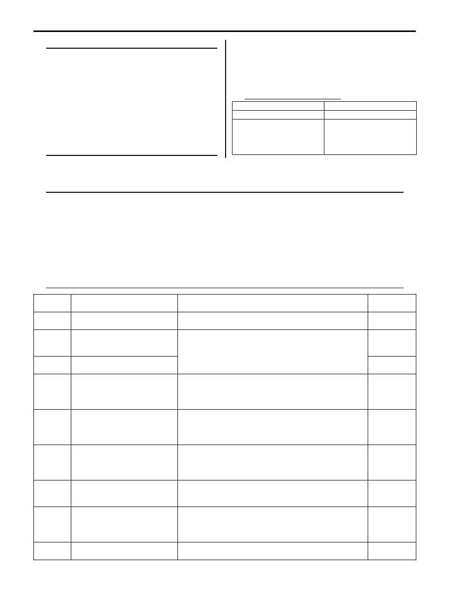
Time required to erase DTC
DTC Table
S5JB0A1104005
NOTE
• For the vehicle equipped with diagnosis connector, some of DTC No. with delta (U) mark in the
following table can not be detected by ECM depending on vehicle specification and local regulation.
• With the generic scan tool, only star (*) marked DTC No. in the following table can be read.
• 1 driving cycle: MIL lights up when DTC is detected during 1 driving cycle.
• 2 driving cycles: MIL lights up when the same DTC is detected also in the next driving cycle after
DTC is detected and stored temporarily in the first driving cycle.
• *2 driving cycles:
MIL blinks or lights up. Refer to “DTC P0300 / P0301 / P0302 / P0303 / P0304: Random Misfire
Detected / Cylinder 1 / Cylinder 2 / Cylinder 3 / Cylinder 4 Misfire Detected” for details.
Ambient temperature
Time to cut power to ECM
Over 0
°C (32 °F)
30 sec. or longer
Under 0
°C (32 °F)
Not specifiable.
Select a place with higher
than 0
°C (32 °F)
temperature.
DTC No.
Detecting item
Detecting condition
(DTC will set when detecting:)
MIL
*P0010
Camshaft position actuator
circuit (for M16 engine)
Oil control valve circuit open or short.
1 driving
cycle
*P0011
Camshaft position – timing
over-advanced or system
performance (for M16 engine)
Actual value of advanced valve timing does not reach
target value, or valve timing is advanced although ECM
command is most retarding.
2 driving
cycles
*P0012
Camshaft position – timing
over-retarded (for M16 engine)
2 driving
cycles
U*P0030
HO2S heater control circuit
(Sensor-1)
Impedance of A/F sensor element is higher than or lower
than specified range for more than 200 sec. even though
A/F sensor heater is turned ON for more than specified
time.
2 driving
cycles
U*P0031
HO2S heater control circuit low
(Sensor-1)
A/F sensor circuit voltage is lower than specification for
more than specified time continuously even though
control duty ratio of A/F sensor heater is less than
specification.
2 driving
cycles
U*P0032
HO2S heater control circuit high
(Sensor-1)
A/F sensor circuit voltage is higher than specification for
more than specified time continuously even though
control duty ratio of A/F sensor heater is more than
specification.
2 driving
cycles
U*P0037
HO2S heater control circuit low
(Sensor-2)
HO2S-2 circuit voltage is lower than specification for more
than specified time continuously even though control duty
ratio of HO2S-2 heater is less than specification.
2 driving
cycles
U*P0038
HO2S heater control circuit high
(Sensor-2)
HO2S-2 circuit voltage is higher than specification for
more than specified time continuously even though
control duty ratio of HO2S-2 heater is more than
specification.
2 driving
cycles
U*P0101
Mass air flow circuit range/
performance
MAF sensor volume is more than specification or less
than specification.
2 driving
cycles

Engine General Information and Diagnosis: 1A-32
*P0102 Mass air flow circuit low input
Output voltage of MAF sensor is less than specification.
1 driving
cycle
*P0103 Mass air flow circuit high input
Output voltage of MAF sensor is more than specification.
1 driving
cycle
U*P0106
Manifold absolute pressure
circuit range/performance
Difference between Max. manifold absolute pressure
value and Min. manifold pressure value is less than
specification or difference between barometric pressure
value and manifold pressure value is less than
specification
2 driving
cycles
*P0107
Manifold absolute pressure
circuit low input
Output voltage of MAP sensor is less than specification.
1 driving
cycle
*P0108
Manifold absolute pressure
circuit high input
Output voltage of MAP sensor is more than specification.
1 driving
cycle
U*P0111
Intake air temperature sensor
circuit range/performance
Variation of intake air temperature from engine start is
less than specification.
2 driving
cycles
*P0112
Intake air temperature sensor
circuit low
Circuit voltage of IAT sensor is less than specification.
1 driving
cycle
*P0113
Intake air temperature sensor
circuit high
Circuit voltage of IAT sensor is more than specification.
1 driving
cycle
U*P0116
Engine coolant temperature
circuit range/performance
Engine coolant temperature is less than specified
temperature for specified time from engine start.
2 driving
cycles
*P0117
Engine coolant temperature
circuit low
Circuit voltage of ECT sensor is less than specification.
1 driving
cycle
*P0118
Engine coolant temperature
circuit high
Circuit voltage of ECT sensor is more than specification.
1 driving
cycle
*P0122
Throttle position sensor (main)
circuit low
Output voltage of throttle position sensor (main) is lower
than specification.
1 driving
cycle
*P0123
Throttle position sensor (main)
circuit high
Output voltage of throttle position sensor (main) is higher
than specification.
1 driving
cycle
U*P0131
O2 sensor (HO2S) circuit low
voltage (Sensor-1)
Output voltage or sensor current of A/F sensor is less
than specification.
2 driving
cycles
U*P0132
O2 sensor (HO2S) circuit high
voltage (Sensor-1)
Output voltage or sensor current of A/F sensor is more
than specification.
2 driving
cycles
U*P0133
O2 sensor (HO2S) circuit slow
response (Sensor-1)
Ratio between integrated value of A/F sensor output
variation and integrated value of short term fuel trim
variation is more than specification.
2 driving
cycles
U*P0134
O2 sensor (HO2S) circuit no
activity detected (Sensor-1)
Impedance of A/F sensor element is higher than
specification for more than 160 sec. even though A/F
sensor heater is turned ON for more than specified time.
2 driving
cycles
U*P0137
O2 sensor (HO2S) circuit low
voltage (Sensor-2)
HO2S-2 voltage is lower than 0.4 V for more than
specified time continuously while vehicle is driving with
high engine load (high speed). And HO2S-2 max. voltage
minus HO2S-2 min. voltage is less than 0.2 V for specified
time continuously.
2 driving
cycles
U*P0138
O2 sensor (HO2S) circuit high
voltage (Sensor-2)
HO2S-2 voltage is higher than 0.85 V for more than
specified time continuously while vehicle is driving with
high engine load (high speed). And HO2S-2 max. voltage
minus HO2S-2 min. voltage is less than 0.2 V for specified
time continuously.
2 driving
cycles
U*P0140
O2 sensor (HO2S) circuit no
activity detected (Sensor-2)
Output voltage of HO2S-2 is more than specification after
warming up engine.
2 driving
cycles
U*P0171
System too lean
Total fuel trim is larger than specification for specified time
or longer. (Fuel trim toward rich side is large.)
2 driving
cycles
U*P0172
System too rich
Total fuel trim is smaller than specification for specified
time or longer. (Fuel trim toward lean side is large.)
2 driving
cycles
*P0222
Throttle position sensor (sub)
circuit low
Output voltage of throttle position sensor (sub) is lower
than specification.
1 driving
cycle
DTC No.
Detecting item
Detecting condition
(DTC will set when detecting:)
MIL
Нет комментариевНе стесняйтесь поделиться с нами вашим ценным мнением.
Текст