Suzuki Grand Vitara JB416 / JB420. Manual — part 19
1A-25 Engine General Information and Diagnosis:
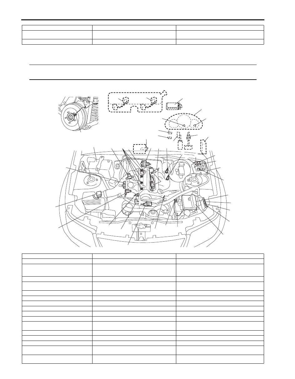
For M16 Engine
NOTE
The figure shows left-hand steering vehicle. For right-hand steering vehicle, parts with (*) are installed
at the opposite side.
15. Rear wheel speed sensor (RH, LH)
(VSS)
16. Electric load current sensor
Information sensors
Control devices
Others
I*
E*
D
H*
B*
e
n
3*
14*
C
J*
g
m
i
c
F
6
5
k
l
f
o
A
G
K
8
4
h
a
d
9
7*
2
1
b
12
10
j
13
15
11
11-1
I5JB0A110017-04
Information sensors
Control devices
Others
1. MAF and IAT sensor
a: Fuel injector
A: ECM
2. Electric throttle body assembly (built-in
throttle position sensor and throttle
actuator)
b: EVAP canister purge valve
B: Combination meter
3. Stop lamp switch
c: Fuel pump relay
C: EVAP canister
4. ECT sensor
d: EGR valve
D: A/C evaporator outlet air temp. sensor (if equipped
with A/C)
5. A/F sensor
e: Malfunction indicator lamp
E: Data link connector
6. Heated oxygen sensor-2
f: Radiator cooling fan relay No.1
F: A/C compressor relay (if equipped)
7. Battery
g: HO2S heater relay
G: ABS hydraulic unit / control module assembly
8. CMP sensor
h: Ignition coil assembly (with ignitor)
H: BCM
9. MAP sensor
i: Main relay
I: Immobilizer coil antenna (if equipped)
10. CKP sensor
j: Oil control valve
J: Fuse box No.2
11. Main fuel level sensor
k: Radiator cooling fan relay No.2
K: A/C refrigerant pressure sensor (if equipped with A/
C)
11-1. Sub fuel level sensor
l: Radiator cooling fan relay No.3
12. Knock sensor
m: Starting motor control relay
13. Power steering pump pressure switch
n: Immobilizer indicator lamp (if equipped)
14. Accelerator pedal position (APP)
sensor
o: Throttle actuator control relay
15. Rear wheel speed sensor (RH, LH)
(VSS)

Engine General Information and Diagnosis: 1A-26
Diagnostic Information and Procedures
Engine and Emission Control System Check
S5JB0A1104001
Refer to the following items for the details of each step.
Step
Action
Yes
No
1
Customer complaint analysis
1) Perform customer complaint analysis referring to
“Customer Complaint Analysis”.
Was customer complaint analysis performed?
Go to Step 2.
Perform customer
complaint analysis.
2
DTC / Freeze frame data check, record and clearance
1) Check for DTC (including pending DTC) referring to
“DTC / Freeze Frame Data Check, Record and
Clearance”.
Is there any DTC(s)?
Print DTC and freeze
frame data or write them
down and clear them by
referring to “DTC
Clearance”, and go to
Step 3.
Go to Step 4.
3
Visual inspection
1) Perform visual inspection referring to “Visual Inspection”.
Is there any faulty condition?
Repair or replace
malfunction part, and go
to Step 11.
Go to Step 5.
4
Visual inspection
1) Perform visual inspection referring to “Visual Inspection”.
Is there any faulty condition?
Repair or replace
malfunction part, and go
to Step 11.
Go to Step 8.
5
Trouble symptom confirmation
1) Confirm trouble symptom referring to “Trouble Symptom
Confirmation”.
Is trouble symptom identified?
Go to Step 6.
Go to Step 7.
6
Rechecking and record of DTC / Freeze frame data
1) Recheck for DTC and freeze frame data referring to
Is there any DTC(s)?
Go to Step 9.
Go to Step 8.
7
Rechecking and record of DTC / Freeze frame data
1) Recheck for DTC and freeze frame data referring to
Is there any DTC(s)?
Go to Step 9.
Go to Step 10.
8
Engine basic inspection and engine symptom
diagnosis
1) Check and repair according to “Engine Basic Inspection”
and “Engine Symptom Diagnosis”.
Are check and repair complete?
Go to Step 11.
Check and repair
malfunction part(s), and
go to Step 11.
9
Troubleshooting for DTC
1) Check and repair according to applicable DTC diag. flow.
Are check and repair complete?
Go to Step 11.
Check and repair
malfunction part(s), and
go to Step 11.
10 ) Intermittent problems check
1) Check for intermittent problems referring to “Intermittent
Problems Check”.
Is there any faulty condition?
Repair or replace
malfunction part(s), and
go to Step 11.
Go to Step 11.

1A-27 Engine General Information and Diagnosis:
Step 1: Customer Complaint Analysis
Record details of the problem (failure, complaint) and how it occurred as described by the customer. For this purpose,
use of such an inspection form will facilitate collecting information to the point required for proper analysis and
diagnosis.
11 ) Final confirmation test
1) Clear DTC if any.
2) Perform final confirmation test referring to “Final
Confirmation Test”.
Is there any problem symptom, DTC or abnormal condition?
Go to Step 6.
End.
Step
Action
Yes
No
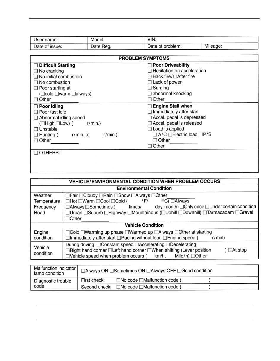
Engine General Information and Diagnosis: 1A-28
Customer problem inspection form (Example)
NOTE
This form is a standard sample. It should be modified according to conditions characteristic of each
market.
I2RH01110010-02
Нет комментариевНе стесняйтесь поделиться с нами вашим ценным мнением.
Текст