Suzuki Grand Vitara JB416 / JB420. Manual — part 18
1A-21 Engine General Information and Diagnosis:
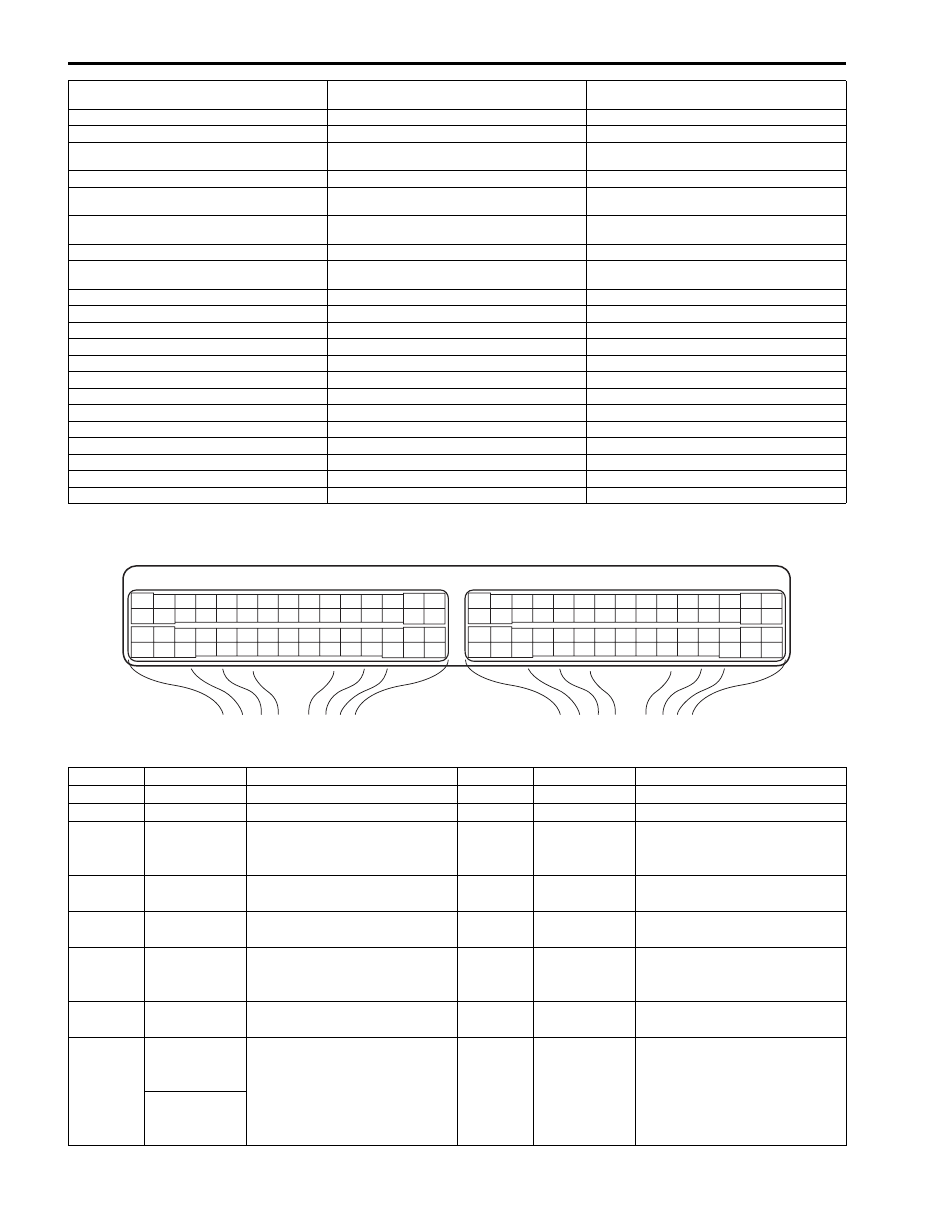
Terminal Arrangement of ECM Coupler (Viewed from Harness Side)
Connector: C37
1. Accelerator pedal position (APP) sensor
assembly
22. Stop lamp switch
44. Radiator cooling fan motor No.1
2. Shield wire
23. Stop lamp
45. Radiator cooling fan motor No.2
3. CMP sensor
24. DLC
46. A/C compressor relay (if equipped with A/C)
4. CKP sensor
25. To BCM and ABS hydraulic unit / control
module assembly
47. A/C compressor (if equipped with A/C)
5. MAF and IAT sensor
26. Barometric pressure sensor
48. “CPRSR” fuse
6. CO adjust resistor (if equipped)
27. Throttle actuator control relay
49. Ignition coil assembly (for No.1 and No.4
spark plugs)
7. MAP sensor
28. “THR MOT” fuse
50. Ignition coil assembly (for No.2 and No.3
spark plugs)
8. ECT sensor
29. Electric throttle body assembly
51. “IG COIL” fuse
9. A/C refrigerant pressure sensor (if equipped
with A/C)
30. Throttle actuator
52. Main relay
10. Generator
31. Throttle position sensor
53. “IG2 SIG” fuse
11. “O2 HTR” fuse
32. Fuel injector No.1
54. “DOME” fuse
12. HO2S heater relay
33. Fuel injector No.2
55. “FI” fuse
13. HO2S-2
34. Fuel injector No.3
56. Ignition switch
14. A/F sensor
35. Fuel injector No.4
57. “IGN” fuse
15. Knock sensor
36. EVAP canister purge valve
58. “STR MOT” fuse
16. Power steering pump pressure switch
37. EGR valve
59. “ST SIG” fuse
17. Immobilizer coil antenna (if equipped)
38. Oil control valve (Camshaft position control)
60. Starting motor control relay
18. ABS hydraulic unit / control module assembly
39. Fuel pump relay
61. Starting motor
19. BCM
40. Fuel pump
62. Diagnosis connector (if equipped)
20. Combination meter
41. Radiator cooling fan relay No.1
63. Battery
21. Main fuel level sensor
42. Radiator cooling fan relay No.2
64. Engine ground
21-1. Sub fuel level sensor
43. Radiator cooling fan relay No.3
65. Body ground
E23
C37
3
4
18
19
5
6
7
10
11
17
20
47
46
49
50
51
21
22
52
16
25
9
24
14
29
55
57
54 53
59
60
58
2
26
27
28
15
30
56
48
32
31
34
35
36
37
40
42
39 38
44
45
43
41
33
1
12
13
23
8
3
4
18
19
5
6
7
10
11
17
20
47
46
49
50
51
21
22
52
16
25
9
24
14
29
55
57
54 53
59
60
58
2
26
27
28
15
30
56
48
32
31
34
35
36
37
40
42
39 38
44
45
43
41
33
1
12
13
23
8
I4RS0A110008-01
Terminal
Wire color
Circuit
Terminal
Wire color
Circuit
1
PNK
Fuel injector No.1
31
BLK/YEL
Ground for A/F sensor heater
2
PNK/BLK
Fuel injector No.2
32
PNK/BLU
Heater output of A/F sensor
3
YEL/GRN
EGR valve (stepper motor coil
3)
33
GRY/RED
Intake manifold tuning vacuum
solenoid valve output
(for J20 engine)
4
YEL
EGR valve (stepper motor coil
4)
34
RED/BLU
Ground for A/F sensor
adjusting resistor
5
YEL/BLK
EGR valve (stepper motor coil
1)
35
RED/YEL
A/F sensor adjusting resistor
signal
6
YEL/RED
EGR valve (stepper motor coil
2)
36
PNK
Crankshaft position (CKP)
sensor (–)
(for J20 engine)
7
BLU/ORN
Power steering pump pressure
switch signal
37
BLK
A/F sensor signal (–)
8
BRN/RED
(for M16
engine)
Generator field coil monitor
signal
38
WHT
A/F sensor signal (+)
BRN/BLK
(for J20
engine)

Engine General Information and Diagnosis: 1A-22
Connector: E23
9
BLU
Electric load current sensor
signal (for J20 engine)
39
—
—
10
GRN/WHT
CO adjusting resistor signal (if
equipped)
40
RED
Throttle position sensor (sub)
signal
11
RED
Oxygen signal of heated
oxygen sensor-2
41
GRN
Ground for throttle position
sensor
12
GRY/BLK
A/C refrigerant pressure
sensor signal (if equipped with
A/C)
42
—
—
13
GRN/BLK
EVAP canister purge valve
output
43
—
—
14
GRY/RED
Output of 5 V power source for
MAP sensor, A/C refrigerant
pressure sensor, electric load
current sensor (for J20 engine)
and CO adjusting resistor (if
equipped)
44
BLU/RED
Output of throttle actuator
15
BLK/ORN
Ground for ECM
45
BLU/YEL
Output of throttle actuator
16
PNK/GRN
Fuel injector No.3
46
—
—
17
PNK/BLU
Fuel injector No.4
47
BLK/RED
Heater output of heated
oxygen sensor-2
18
BRN/YEL
Ignition coil No.4
(for J20 engine)
48
BLK/YEL
Ground for ECM
19
BRN/WHT
Ignition coil No.3
(for J20 engine)
49
—
—
20
BRN/BLK
Ignition coil No.2 and No.3
(for M16 engine)
50
—
—
Ignition coil No.2
(for J20 engine)
21
BRN
Ignition coil No.1 and No.4
(for M16 engine)
51
WHT/BLU
CKP sensor signal (for M16
engine)
Ignition coil No.1
(for J20 engine)
BLU
Crankshaft position (CKP)
sensor (+)
(for J20 engine)
22
BLK/YEL
Starting motor signal
52
WHT/RED
CMP sensor signal
23
—
—
53
WHT
Output for 5 V power source of
throttle position sensor
24
PPL/YEL
Engine coolant temp. (ECT)
sensor signal
54
BLK
Throttle position sensor (main)
signal
25
LT GRN
Intake air temp. (IAT) sensor
signal
55
RED/WHT
Manifold absolute pressure
(MAP) sensor signal
26
RED
Mass air flow (MAF) sensor
signal
56
WHT
Knock sensor signal
27
BLU
Ground for MAF sensor
57
GRY/GRN
Ground for sensors
28
BRN/BLK
Generator control signal output
58
BLK/YEL
Ground for ECM
29
BLK/YEL
Ground for ECM
59
BRN/YEL
Oil control valve ground
(for M16 engine)
30
BLK/ORN
Ground for ECM
60
BRN/WHT
Oil control valve output
(for M16 engine)
Terminal
Wire color
Circuit
Terminal
Wire color
Circuit
Terminal
Wire color
Circuit
Terminal
Wire color
Circuit
1
BLU/BLK
Main power supply
31
—
—
2
WHT
Power source for ECM internal
memory
32
—
—
3
—
—
33
—
—

1A-23 Engine General Information and Diagnosis:
4
WHT/RED
CAN (high) communication line
(active high signal) to ABS
hydraulic unit / control module
assembly
34
—
—
5
PPL/WHT
12 V serial communication line
of data link connector
35
—
—
6
BLK/WHT
Cruise control main switch
signal (if equipped with cruise
control system)
36
—
—
7
BLU
Clutch pedal position switch
signal (if equipped with cruise
control system)
37
—
—
8
YEL/GRN
Brake pedal position switch (if
equipped with cruise control
system)
38
—
—
9
—
—
39
—
—
10
—
—
40
—
—
11
—
—
41
—
—
12
YEL
Diagnosis switch terminal (if
equipped)
42
—
—
13
PNK/BLU
Clock signal for immobilizer
coil antenna (if equipped)
43
—
—
14
—
—
44
—
—
15
WHT/GRN
Fuel pump relay output
45
—
—
16
BLU/BLK
Main power supply
46
RED/BLK
Radiator cooling fan relay No.1
output
17
GRN
Power supply of throttle
actuator drive circuit
47
RED
Radiator cooling fan relay No.2
output
18
—
—
48
RED/YEL
Radiator cooling fan relay No.3
output
19
WHT/BLU
CAN (low) communication line
(active low signal) to ABS
hydraulic unit / control module
assembly
49
PNK
A/C compressor relay output (if
equipped with A/C)
20
GRN/WHT
Stop lamp switch signal
50
BLU/ORN
Throttle actuator control relay
output
21
BLK/YEL
Cruise control command
switch ground (if equipped with
cruise control system)
51
BLU/YEL
Ground for accelerator pedal
position (APP) sensor (sub)
22
LT GRN
Cruise control command
switch signal (if equipped with
cruise control system)
52
BLU/GRN
Accelerator pedal position
(APP) sensor (sub) signal
23
—
—
53
ORN/BLU
Output for 5 V power source of
accelerator pedal position
(APP) sensor (sub)
24
YEL/RED
Fuel level sensor signal
54
ORN
Ground for accelerator pedal
position (APP) sensor (main)
25
—
—
55
WHT/BLU
Accelerator pedal position
(APP) sensor (main) signal
26
—
—
56
WHT
Output for 5 V power source of
accelerator pedal position
(APP) sensor (main)
27
—
—
57
—
—
28
GRY/BLU
Serial communication line for
immobilizer coil antenna (if
equipped)
58
—
—
29
BLK/WHT
Ignition switch signal
59
—
—
30
—
—
60
BLU
Main power supply relay output
Terminal
Wire color
Circuit
Terminal
Wire color
Circuit

Engine General Information and Diagnosis: 1A-24
Component Location
Electronic Control System Components Location
S5JB0A1103001
For J20 Engine
NOTE
The figure shows left-hand steering vehicle. For right-hand steering vehicle, parts with (*) are installed
at the opposite side.
I*
E*
11
F*
G*
D
H*
B*
e
n
3*
14*
C
A
15
h
1
2
12
J*
L
16*
7*
a
9
d
4
8
10
6
5
j
m
i
c
g
k
l
f
o
K
13
b
11-1
I5JB0A110016-04
Information sensors
Control devices
Others
1. MAF and IAT sensor
a: Fuel injector
A: ECM
2. Electric throttle body assembly (built-in
throttle position sensor and throttle
actuator)
b: EVAP canister purge valve
B: Combination meter
3. Stop lamp switch
c: Fuel pump relay
C: EVAP canister
4. ECT sensor
d: EGR valve
D: A/C evaporator outlet air temp. sensor (if equipped
with A/C)
5. A/F sensor
e: Malfunction indicator lamp
E: Data link connector
6. Heated oxygen sensor-2
f: Radiator cooling fan relay No.1
F: 4WD control module
7. Battery
g: IMT vacuum solenoid valve
G: TCM (for A/T model)
8. CMP sensor
h: Ignition coil assembly (with ignitor)
H: BCM
9. MAP sensor
i: Main relay
I: Immobilizer coil antenna (if equipped)
10. CKP sensor
j: Integration relay No.2 (built-in HO2S heater
relay, compressor relay and A/T relay)
J: Fuse box No.2
11. Main fuel level sensor
k: Radiator cooling fan relay No.2
K: A/C refrigerant pressure sensor (if equipped with A/
C)
11-1. Sub fuel level sensor
l: Radiator cooling fan relay No.3
L: ABS hydraulic unit / control module assembly
12. Knock sensor
m: Starting motor control relay
13. Power steering pump pressure switch
n: Immobilizer indicator lamp (if equipped)
14. Accelerator pedal position (APP)
sensor
o: Throttle actuator control relay
Нет комментариевНе стесняйтесь поделиться с нами вашим ценным мнением.
Текст