Suzuki Grand Vitara JB416 / JB420. Manual — part 236
5A-78 Automatic Transmission/Transaxle:
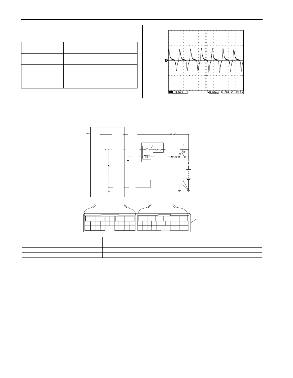
Reference Waveform No. 5
Input shaft speed sensor signal at engine speed 3000
rpm.
TCM Power and Ground Circuit Check
S5JB0A5104062
Wiring Diagram
Measurement
terminal
CH1: “E93-6” to “E92-1”
Oscilloscope
setting
CH1: 2 V/DIV
TIME: 10 ms/DIV
Measurement
condition
• After warmed up to normal
operating temperature
• Engine at 3,000 rpm with “P”
range.
I5JB0A510047-02
BLK
BLK
BLK
E92-1
E92-23
E92-6
BLK/WHT
BLK/WHT
WHT/GRN
E92-24
WHT
1
2
3
4
7
6
5
6
5
16 15 14 13 12 11
4 3
24 23
21
22
10 9
8
7
2
1
19
20
18 17
E92
17 16
26 25
15 14
6
5
3
4
2
13 12
23 22
24
11 10 9
21 20 19
8 7
18
1
E93
8
I5JB0A510152-01
1. TCM
5. Ignition switch
2. A/T relay
6. “IG COIL” fuse
3. “AT” fuse
7. Power integration No.2 in main fuse box
4. “DOME” fuse
8. Terminal arrangement of TCM connector (viewed from harness side)

Automatic Transmission/Transaxle: 5A-79
Troubleshooting
Step
Action
Yes
No
1
Check TCM back-up power circuit
1) Disconnect TCM connector with ignition switch OFF.
2) Check for proper connection to TCM at “E92-24”
terminal.
3) If OK, check voltage at terminal “E92-24” of
disconnected TCM connector.
Is it 10 – 14 V?
Go to Step 2.
“WHT” circuit open or
shorted to ground.
2
Check TCM power circuit
1) Disconnect TCM connector with ignition switch OFF.
2) Check for proper connection to TCM at “E92-6” terminal.
3) If OK, turn ignition switch ON and check voltage at
terminal “E92-6” of disconnected TCM connector.
Is it 10 – 14 V?
Go to Step 4.
Go to Step 3.
3
Check A/T relay operation
1) Check A/T relay operation referring to “A/T Relay
Is check result satisfactory?
“BLK/WHT”, “WHT/
GRN”, or “BLK” circuit
for power supply open.
Replace A/T relay
included in power
integration No.2 in main
fuse box.
4
Check TCM ground circuit
1) Turn ignition switch OFF.
2) With TCM connectors disconnected, check for proper
connection to TCM at “E92-1” / “E92-23” terminal.
3) If OK, check resistance between “E92-1” / “E92-23”
terminal of disconnected TCM connector and body
ground.
Is continuity indicated?
TCM power and ground
circuits are in good
condition.
“BLK” circuit for TCM
ground open.
5A-80 Automatic Transmission/Transaxle:
Repair Instructions
A/T Fluid Level Check
S5JB0A5106041
At Normal Operating Temperature
1) Drive vehicle so that A/T fluid temperature reach the
normal operating temperature (70 – 80
°C (158 –
176
°F)).
2) Stop vehicle with engine running and place it level.
3) With select lever at “P” range, apply parking brake
and place chocks against wheels.
4) Keep engine idling and shift selector slowly to “L”
and back to “P” range.
5) With engine idling, pull out dipstick (1), wipe it off
with a clean cloth and put it back into place.
6) Pull out dipstick (1) again and check fluid level
indicated on it. Fluid level should be between FULL
HOT and LOW HOT. If it is below LOW HOT, add
specified A/T fluid up to FULL HOT.
A/T fluid specification
SUZUKI ATF 3317 or Mobil ATF 3309
NOTE
• DO NOT RACE ENGINE while checking
fluid level, even after engine is started.
• DO NOT OVERFILL. Overfilling can causes
foaming and loss of fluid through breather.
Then slippage and transmission failure can
result.
• If vehicle was driven under high load such
as pulling a trailer, fluid level should be
checked about half an hour after it is
stopped.
• When checking oil level, oil level gauge
must be used in proper direction. Insert oil
level gauge so that its front or back face is
directed to the front of vehicle. When oil
level indicated on front face of oil level
gauge differs from that on back face, use
lower one.
At Room Temperature
The fluid level check at room temperature performed
after repair or fluid change before test driving is just
preparation for level check of normal operating
temperature. The checking procedure itself is the same
as that described in “At Normal Operating Temperature”
under “A/T Fluid Level Check”. If the fluid level is
between FULL COLD and LOW COLD, proceed to test
drive. And when the fluid temperature has reached the
normal operating temperature, check fluid level again
and adjust it as necessary.
2. “FULL HOT”
4. “FULL COLD”
3. “LOW HOT”
5. “LOW COLD”
1. Dipstick
3. “LOW COLD”
2. “FULL COLD”
I5JB0A510028-02
I5JB0A510029-02
Automatic Transmission/Transaxle: 5A-81
A/T Fluid Change
S5JB0A5106042
1) Lift up vehicle.
2) When engine is cool, remove drain plug (1) from oil
pan and drain A/T fluid.
3) Install drain plug with new gasket.
Tightening torque
A/T fluid drain plug (a): 20 N·m (2.0 kgf-m, 14.5
lb-ft)
4) Lower vehicle and fill proper amount of specified
fluid.
5) Check fluid level referring to “At Normal Operating
Temperature” under “A/T Fluid Level Check”.
A/T fluid specification
: SUZUKI ATF 3317 or Mobil ATF 3309
A/T fluid capacity reference value
When draining from drain plug hole: Approx. 2.5
liters (5.33/4.40 US/lmp. pt.)
When overhauling: Approx. 7.2 liters (15.36/12.67
US/lmp. pt.)
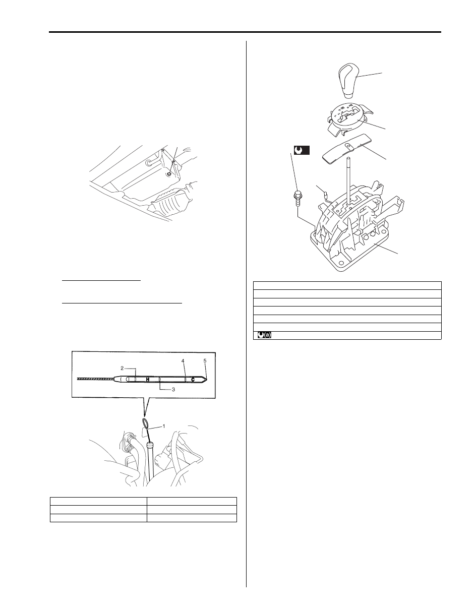
Manual Selector Assembly Components
S5JB0A5106043
1. Dipstick
4. “FULL COLD”
2. “FULL HOT”
5. “LOW COLD”
3. “LOW HOT”
1, (a)
I5JB0A510030-03
I5JB0A510031-02
1. Manual lever assembly
2. Select indicator assembly
3. Illumination lamp assembly
4. Knob
5. Manual selector assembly mounting bolt
6. Slide cover
: 17.5 N
⋅m (1.75 kgf-m, 13.0 lb-ft)
4
2
6
1
5
(a)
3
I5JB0A510033-01
Нет комментариевНе стесняйтесь поделиться с нами вашим ценным мнением.
Текст