Suzuki Grand Vitara JB416 / JB420. Manual — part 237
5A-82 Automatic Transmission/Transaxle:
Manual Selector Assembly Removal and
Installation
S5JB0A5106044
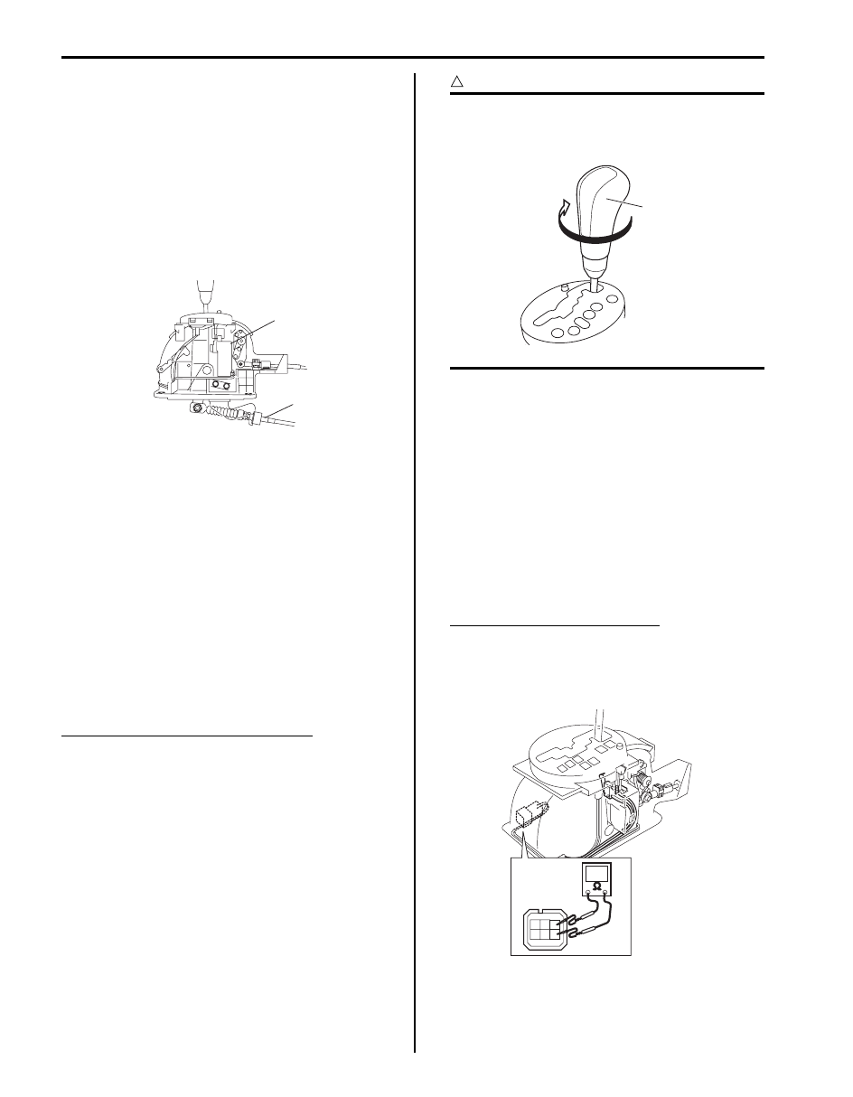
Removal
1) Disconnect negative cable at battery.
2) Remove front console box.
3) Disconnect shift lever switch connector.
4) Remove manual selector assembly mounting bolts.
5) Disconnect select cable (1) from manual selector
assembly (2).
Installation
Reverse removal procedure to install manual selector
assembly noting the following instructions.
• Tighten manual selector assembly mounting bolts to
specified torque.
Tightening torque
Manual selector assembly mounting bolt: 18 N·m
(1.8 kgf-m, 13.0 lb-ft)
• Adjust select cable referring to “Select Cable
Select Lever Knob Installation
S5JB0A5106045
Screw select lever knob onto select lever by specified
numbers of rotation below.
Rotation numbers for select lever knob
Installation (a): 13 – 14 rotations
CAUTION
!
When installing select lever knob, do not turn
more than specified numbers of rotation.
Otherwise select lever knob is damaged.
Manual Selector Assembly Inspection
S5JB0A5106046
Check select lever for smooth and clear-cut movement
individually and position indicator for correct indication.
If a malfunction is found, replace select lever assembly.
“3” Position Switch Inspection
S5JB0A5106091
1) Disconnect negative cable at battery.
2) Remove front console box.
3) Disconnect manual selector connector (1).
4) Measure resistance between “3” position switch
terminals.
“3” position switch specification
Shift selector lever to “P”, “N” or “D” range: 3.96
– 4.04 k
Ω
Shift selector lever to “R”, “3”, “2” or “L” range:
0.99 – 1.01 k
Ω
1
2
I5JB0A510034-02
1,(a)
I4RS0A510058-01
I5JB0A510164-01

Automatic Transmission/Transaxle: 5A-83
Select Cable Component
S5JB0A5106047
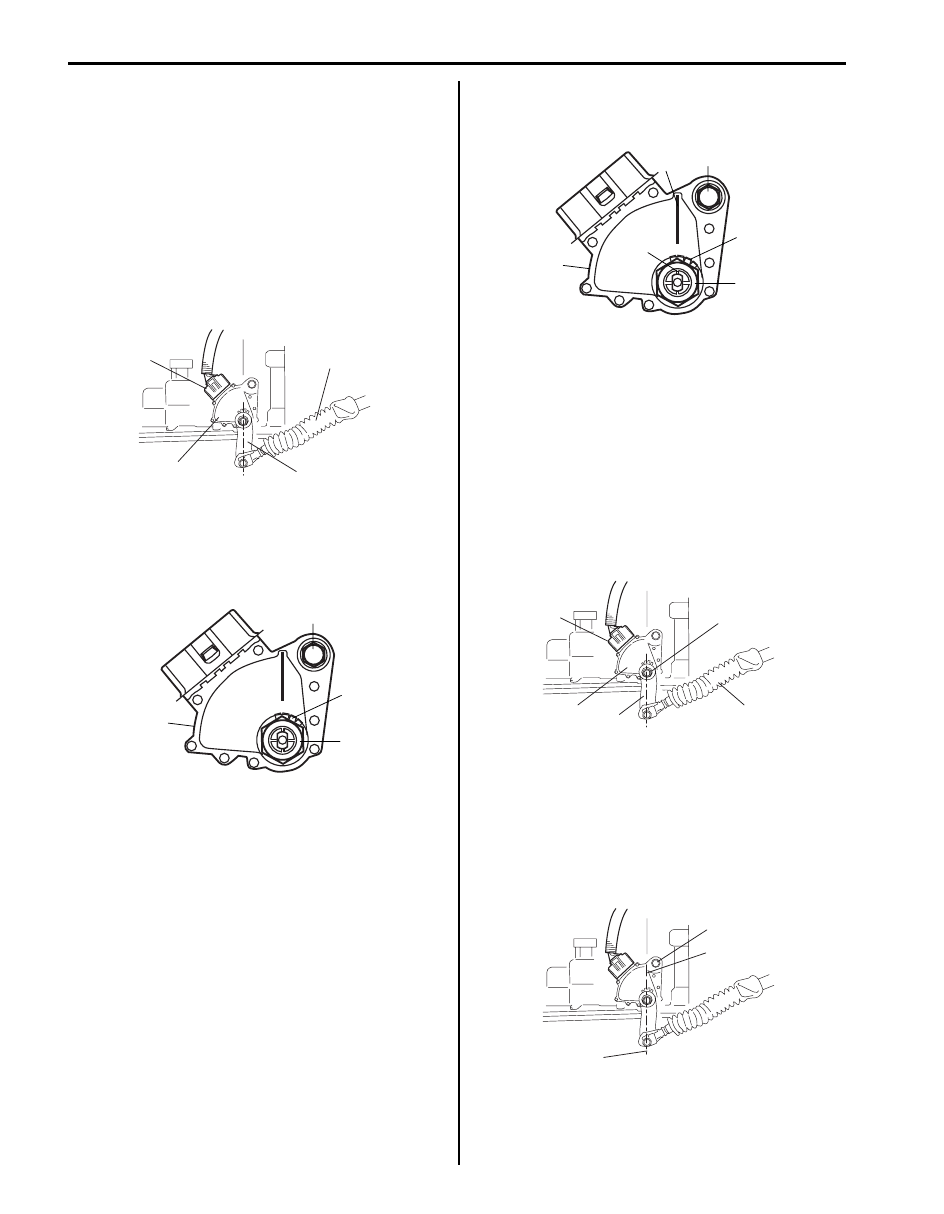
Select Cable Adjustment
S5JB0A5106048
1) Loosen manual select cable nut.
2) Shift select lever to “N”.
3) Align center line (1) on manual shift shaft (2) to “N”
reference line (3) as shown in figure.
4) Tighten manual select cable nut (1) to specified
torque.
Tightening torque
Manual select cable nut (a): 13 N·m (1.3 kgf-m,
9.5 lb-ft)
5) After select cable was adjusted, check for the
following.
• Push vehicle with selector lever shifted to “P”.
Vehicle should not move.
• Vehicle can not be driven in “N”.
• Vehicle can be driven in “D”, “3”, “2” and “L”.
• Vehicle can be backed in “R”.
1
2
3
4
5
6
7
8
9
(a)
(b)
(c)
(d)
I5JB0A510035-01
1. Manual selector assembly
6. Manual select cable nut
: 13 N
⋅m (1.3 kgf-m, 9.5lb-ft)
2. Manual selector assembly mounting bolt
7. Manual select lever nut
: 12.5 N
⋅m (1.25 kgf-m, 9.0 lb-ft)
3. Select cable
8. Transmission range sensor
: 5.3 N
⋅m (0.53 kgf-m, 4.0 lb-ft)
4. Select cable bracket
9. Transmission range sensor bolt
5. Manual select lever
: 17.5 N
⋅m (1.75 kgf-m, 13.0 lb-ft)
1
2
3
I5JB0A510038-02
1, (a)
I5JB0A510036-02
5A-84 Automatic Transmission/Transaxle:
Transmission Range Sensor Removal and
Installation
S5JB0A5106049
Removal
1) Disconnect negative cable at battery.
2) Hoist vehicle.
3) Disconnect transmission range sensor connector
(1).
4) Disconnect select cable (2) from manual select lever
(3).
5) Remove manual select lever (3) from transmission
range sensor (4).
6) Unbend bend parts of lock washer (1), then remove
manual shift shaft nut (2), lock washer (1) and
grommet.
7) Remove transmission range sensor (3) by removing
sensor bolt (4).
Installation
1) Install transmission range sensor (3) and tighten
sensor bolt (4) temporarily.
2) Install grommet, lock washer (1) and manual shift
shaft nut (2).
Tighten nut to specified torque. After tightening it,
bend claws of lock washer (1).
Tightening torque
Manual shift shaft nut (a): 12.5 N·m (1.25 kgf-m,
9.0 lb-ft)
3) After turning manual shift shaft fully
counterclockwise, turn it clockwise by 2 notches and
set it to “N” range.
4) With “N” reference line (5) on range sensor and shaft
center (6) aligned, tighten transmission range sensor
bolt (4) to specified torque.
Tightening torque
Transmission range sensor bolt (b): 5.3 N·m (
0.53 kgf-m, 4.0 lb-ft)
5) Install manual select lever (3) to transmission range
sensor (4).
Tighten nut to specified torque.
Tightening torque
Manual select lever nut (a): 12.5 N·m (1.25 kgf-
m, 9.0 lb-ft)
6) Connect select cable (2) to manual select lever (3).
7) Connect transmission range sensor connector (1).
8) Connect negative cable at battery.
9) Adjust select cable referring to “Select Cable
Transmission Range Sensor Inspection and
Adjustment
S5JB0A5106050
1) Manual select lever to “N” range.
2) Check that center line (2) on manual shift and “N”
reference line (1) on sensor are aligned. If not,
loosen sensor bolt (3) and align them.
1
2
3
4
I5JB0A510037-01
4
3
1
2
I4JA01512011-01
6
5
4, (b)
3
1
2, (a)
I4JA01512012-01
2
3
4
(a)
1
I5JB0A510039-02
1
3
2
I5JB0A510040-01
Automatic Transmission/Transaxle: 5A-85
3) Check that engine starts in “N” and “P” ranges but it
doesn’t start in “D”, “3”, “2”, “L” or “R” range. Also,
check that back-up lamp lights in “R” range.
If faulty condition cannot be corrected by adjustment,
disconnect transmission range sensor connector
and check that continuity exists as shown by moving
select lever.
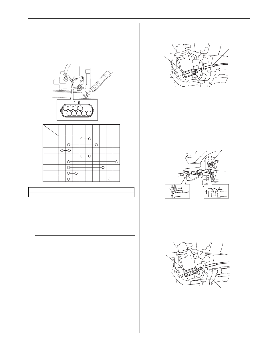
Key Interlock Cable Removal and Installation
S5JB0A5106051
NOTE
Do not bend interlock cable excessively
when removing and installing it, or system
will not operate correctly.
Removal
1) Disconnect negative (–) cable from battery.
2) If equipped with air bag system, disable air bag
system. Refer to “Disabling Air Bag System in
Section 8B”.
3) Remove steering column hole cover.
4) Tilt steering column if steering column is adjustable.
If no adjustable, loosen steering column bolts.
5) Remove steering column cover.
6) Turn ignition switch to ACC position.
7) Pull out key interlock cable (1) from key cylinder
cover (2) while pressing checkhook with slotted
screwdriver or the like.
8) Turn ignition switch to LOCK position.
9) Remove front console box.
10) Detach cable end (1) from interlock cam (2) while
pressing claws (3) of interlock cam boss.
At this time, be careful not to cause damage to its
claws.
Detach cable casing cap (4) from selector bracket
(5) while pressing checkhook.
11) Remove interlock cable.
Installation
1) Lay interlock cable to its original cabling route.
2) Turn ignition switch to “ACC” position.
3) Insert cable casing cap (1) into key cylinder cover (2)
securely.
[A]: Sensor position
[B]: Terminal No.
1
2
3
4
5
6
7
8
9
P
R
N
D
and
3
2
L
1
2
3
4
5
6
7
8
9
[B]
[A]
I5JB0A510041-02
2
1
I5JB0A510062-01
4
5
3
2
1
I5JB0A510063-01
2
1
I5JB0A510064-01
Нет комментариевНе стесняйтесь поделиться с нами вашим ценным мнением.
Текст