Suzuki Grand Vitara JB416 / JB420. Manual — part 394
9I-3 Sun Roof / T-Top / Convertible Top:
Sliding (Sun) Roof Motor Removal and
Installation
S5JB0A9906006
Removal
1) Remove spot lamp assembly from head lining.
2) Disconnect coupler (3) and remove sliding roof
motor (1) by removing 2 bolts (2).
Installation
For installation, reverse removal procedure, noting the
following points.
• Connect coupler to sliding roof motor securely.
• Initialize sliding roof position data referring to “How to
reactivate the system to prevent being pinched by the
sunroof” in Sunroof section of Owner’s manual.
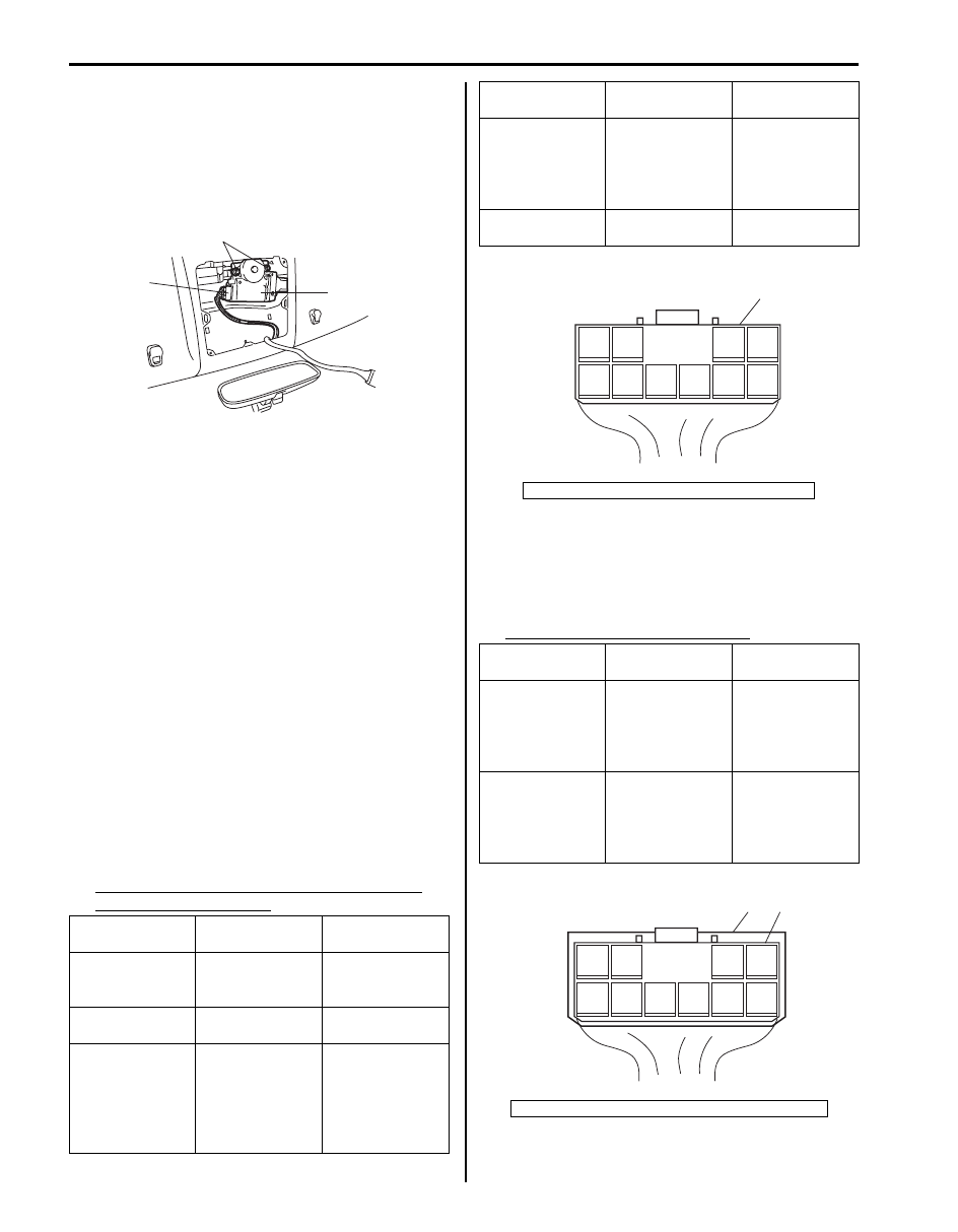
Sliding (Sun) Roof System Circuit and Motor
Inspection
S5JB0A9906007
1) Check that sliding roof switch is in good condition
referring to “Sliding (Sun) Roof Switch Inspection”.
2) Connect connector to sliding roof switch.
3) Disconnect connector from sliding roof motor.
4) Measure voltage and resistance between each
terminals of sliding roof motor connector (1).
If each voltage and/or resistance are within specified
value, sliding roof system circuit is in good condition
and proceed next step.
If each voltage and/or resistance are out of specified
value, repair sliding roof system circuit.
Sliding roof system circuit specification with
connector disconnected
5) Connect connector to sliding roof motor (1).
6) Measure each voltage between terminals of sliding
roof motor connector (2) with ignition switch ON.
If each voltage is out of specified value, replace
sliding roof motor.
Sliding roof motor out put voltage
Measurement
terminal
Measurement
condition
Reference value
5(+) – 7(–)
Ignition switch
turned OFF and
ON
10 – 14 V
8(+) – 7(–)
Ignition switch
turned ON
10 – 14 V
9 – 7
Ignition switch
turned OFF and
sliding roof
switch from OFF
to “SLIDE
OPEN”
Infinity
↓
0 – 1
Ω
2
3
1
I5JB0A990006-01
10 – 7
Ignition switch
turned OFF and
sliding roof
switch from OFF
to “TILT UP”
Infinity
↓
0 – 1
Ω
7 – vehicle body
ground
Ignition switch
turned OFF
0 – 1
Ω
[A]: Viewed from harness side
Measurement
terminal
Measurement
condition
Reference value
9(+) – 7(–)
Sliding roof
switch from OFF
to “SLIDE
OPEN”
10 – 14 V
(OFF)
↓
0 V
(“SLIDE OPEN”)
10(+) – 7(–)
Sliding roof
switch from OFF
to “TILT UP”
10 – 14 V
(OFF)
↓
0 V
(“TILT UP”)
[A]: Viewed from harness side
Measurement
terminal
Measurement
condition
Reference value
1
2
3
4
5
6
9
8
7
10
1
[A]
I5JB0A990007-01
1
2
3
4
5
6
9
8
7
10
1
2
[A]
I5JB0A990008-01
Sun Roof / T-Top / Convertible Top: 9I-4
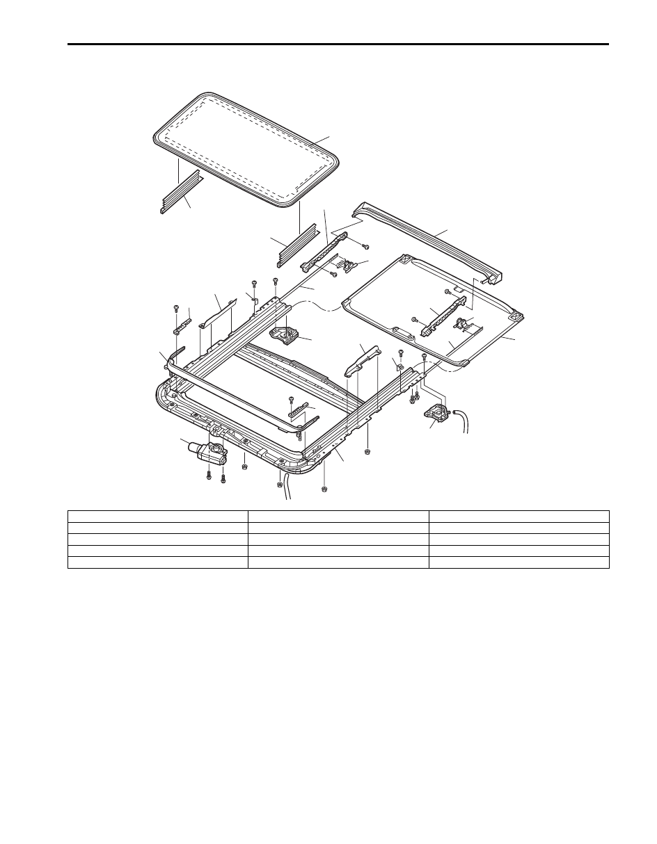
Sliding (Sun) Roof Assembly Components
S5JB0A9906008
1
2
2
8
9
10
12
13
14
5
4
3
14
13
12
8
9
7
10
6
11
11
I5JB0A990009-02
1. Sliding roof glass
6. Sunshade
11. No.1 peace
2. Sliding roof cover
7. Drip channel
12. Rail stopper
3. Sliding roof housing
8. Panel bracket
13. Housing cover
4. Sliding roof motor
9. Shoe
14. Guide block
5. Deflector
10. Drive cable
9I-5 Sun Roof / T-Top / Convertible Top:
Sliding (Sun) Roof Assembly Removal and
Installation
S5JB0A9906009
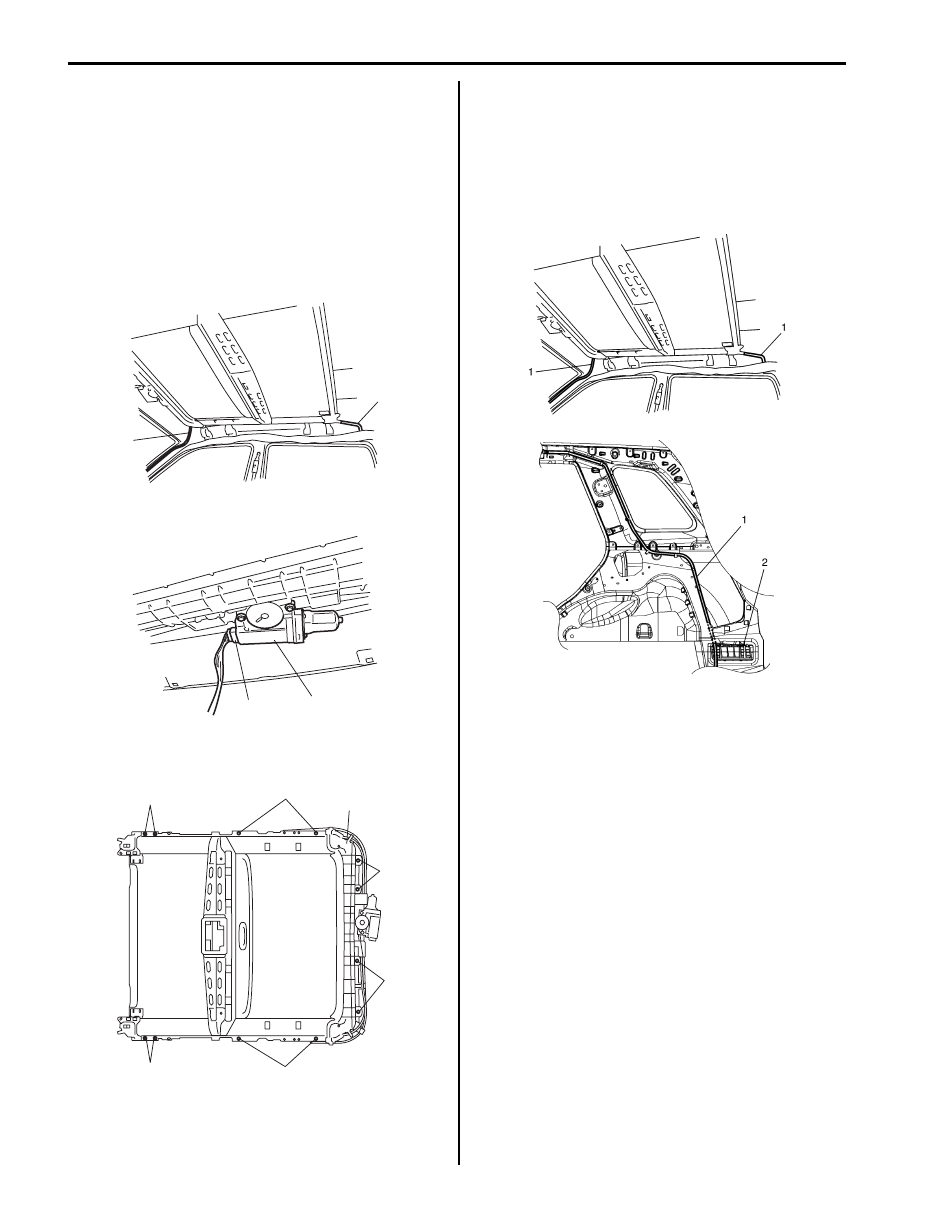
Removal
1) Remove head lining referring to “Head Lining
Removal and Installation in Section 9H”.
2) Remove sliding roof glass referring to “Sliding (Sun)
Roof Glass Removal and Installation”.
3) Disconnect drain hoses (1) connected to sliding roof
assembly at 4 locations.
4) Disconnect sliding roof motor (1) at coupler (2).
5) Remove 8 nuts (1) and 4 bolts (2), then remove
sliding roof assembly (3).
Installation
For installation, reverse removal procedure, noting the
following points.
• Connect drain hoses (1) to sliding roof assembly at 4
locations. Clamp drain hose by each clamp securely.
• Pass rear drain hose between rib of outlet ventilator
(2).
• Initialize sliding roof position data referring to “How to
reactivate the system to prevent being pinched by the
sunroof” in Sunroof section of Owner’s manual.
• After reinstalling sliding roof assembly, be sure to
make glass adjustment. (Refer to “Sliding (Sun) Roof
Glass Adjustment”.)
1
1
I5JB0A990010-01
1
2
I5JB0A990011-01
1
1
1
1
2
2
3
I5JB0A990012-01
I5JB0A990013-01
Sun Roof / T-Top / Convertible Top: 9I-6
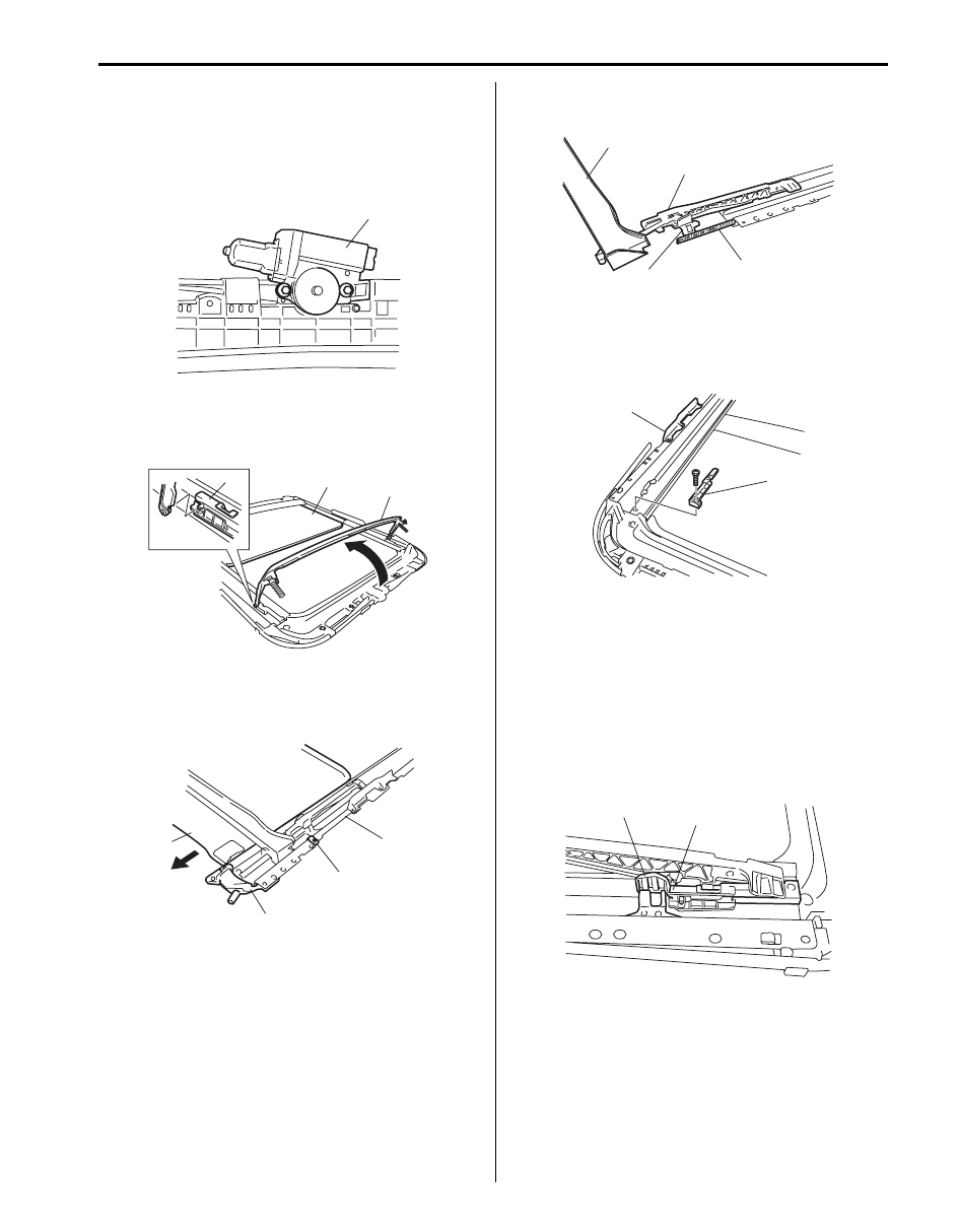
Sliding (Sun) Roof Assembly Disassembly and
Reassembly
S5JB0A9906010
Disassembly
1) Remove sliding roof motor (1).
2) Slide sunshade (1) to full-position.
3) Remove deflector (2) from holder (3) with holding
deflector.
4) Remove No.1 peaces (1) and then pull out sunshade
(2) from guide rails (3).
5) Remove rail stoppers (4) from guide rails.
6) Pull out drip channel (1), panel brackets (2), shoes
(3) and drive cables (4) all together from guide rails.
7) Disassemble drip channel, panel brackets, shoes
and drive cables.
8) Remove guide block (1) and housing covers (2) from
rails.
Reassembly
Reverse disassembly procedure for reassembly, noting
the following.
• Check wear and damage of drive cables and sliding
roof motor gear.
• Apply grease to sliding part.
• Slide shoes (1) to contact guide blocks (2) for
positioning the sliding roof to tilt up position and install
sliding roof motor.
1
I5JB0A990014-01
1
2
3
I5JB0A990015-01
1
2
3
4
I5JB0A990016-01
1
2
3
4
I5JB0A990017-01
1
2
I5JB0A990018-01
1
2
I5JB0A990019-01
Нет комментариевНе стесняйтесь поделиться с нами вашим ценным мнением.
Текст