Suzuki Grand Vitara JB416 / JB420. Manual — part 392
9G-2 Seats:
Front Seat Removal and Installation
S5JB0A9706002
Removal
1) Disable air bag system referring to “Disabling Air
2) Disconnect seat harness coupler, seat heater
coupler and side air bag coupler, if equipped.
3) Remove 4 mounting bolts to remove seat assembly.
4) Disassemble and repair seat as necessary.
Installation
Reverse removal procedure to install front seat.
• Torque to specifications as shown in “Front Seat
• Enable air bag system referring to “Enabling Air Bag
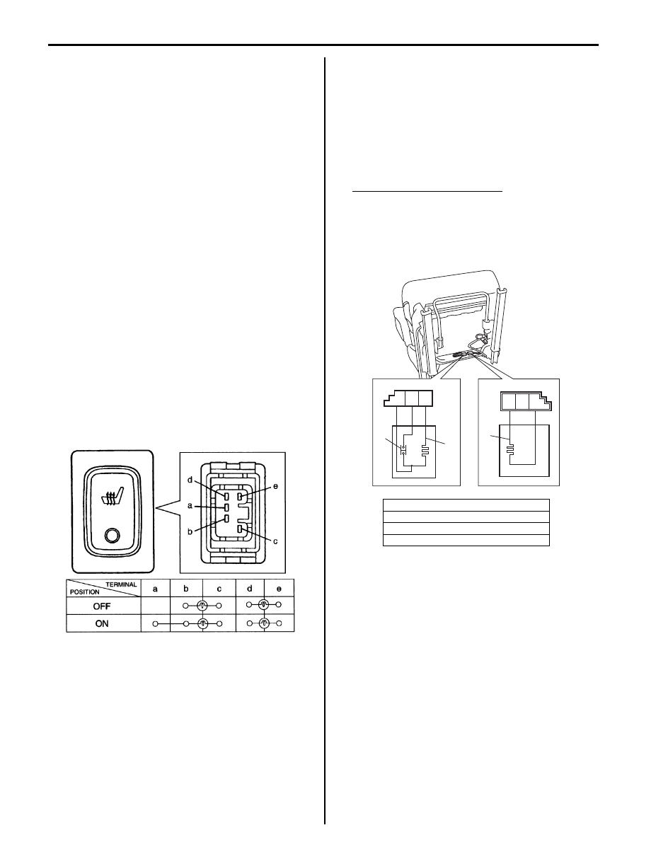
Front Seat Heater Switch (Driver and Passenger
Side) Inspection (If Equipped)
S5JB0A9706005
1) Confirm that ignition switch is OFF position.
2) Detach gear shift panel from front center console
box.
3) Disconnect seat heater switch coupler.
4) Check for continuity between terminals at each
switch position as shown below. If check result is not
as specified, replace.
Front Seat Heater Wire Inspection (If Equipped)
S5JB0A9706006
1) Confirm that seat heater switch is OFF position.
2) Disconnect coupler of seat heater under the seat
cushion.
3) Measure resistance between terminals as shown
below. If resistance is out of specification, replace
faulty seat cushion and/or seat back including seat
heater.
Seat heater circuit resistance
Seat cushion side [A] (between terminal “B” and
“C”, between terminal “A” and “C”): 4.7 – 5.7
Ω
(at 20
°C, 68 °F)
Seat back side [B] (between terminal “F” and
“D”: 10.7 – 13.1
Ω (at 20 °C, 68 °F)
I5JA01970001-01
1. Heater wire
2. Thermostat
[A]: Seat cushion side
[B]: Seat back side
A
B
C
D
E
F
[A]
[B]
1
1
2
I5JB0A970002-01
Seats: 9G-3
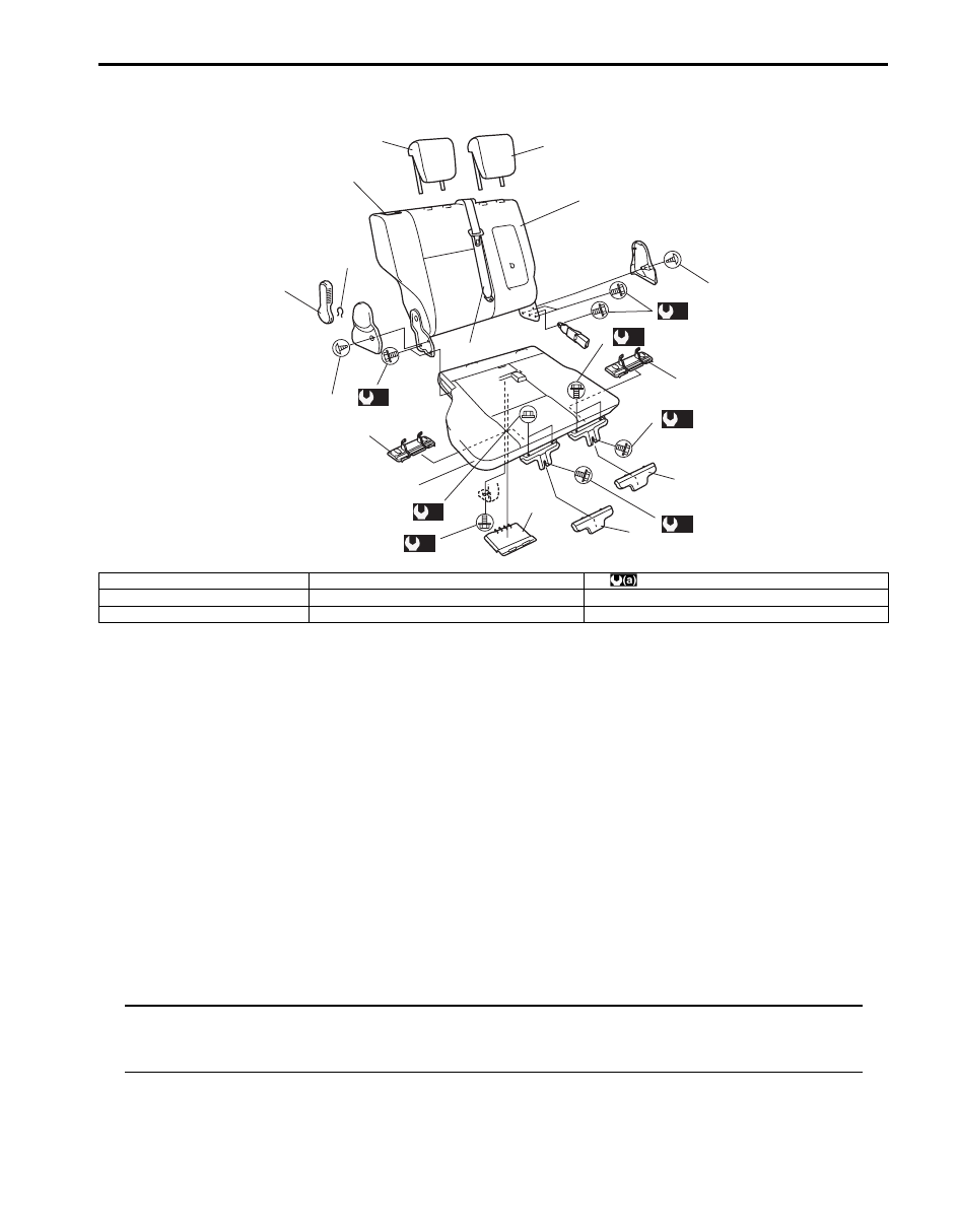
Rear Seat Components
S5JB0A9706003
Rear Seat Removal and Installation
S5JB0A9706004
Removal
1) Remove seat mounting bolt(s) in the bracket.
2) Fold rear seat back and unlock the seat cushion lock to pull forward the seat cushion.
3) Remove seat mounting nuts (bolts) to remove rear seat assembly.
4) Disassemble and repair seat as necessary.
Installation
Reverse removal procedure to install rear seat.
• Torque to specifications in “Rear Seat Components”.
Specifications
Tightening Torque Specifications
S5JB0A9707001
NOTE
The specified tightening torque is also described in the following.
“Front Seat Components”
“Rear Seat Components”
Reference:
For the tightening torque of fastener not specified in this section, refer to “Fastener Information in Section 0A”.
*3
*6
**6
*
*
*4
*4
*5
1
2
3
4
4
*4
(a)
*
(a)
*
(a)
(a)
*
(a)
(a)
(a)
**
I5JB0A970003-01
1. Seat cushion
4. Cover
: 35 N
⋅m (3.5 kgf-m, 25.5 lb-ft)
2. Seat back
5. Rear center seat belt
*: 5 door model
3. Headrestraint
6. Reclining lever
**: 3 door model
9H-1 Interior Trim:
Body, Cab and Accessories
Interior Trim
Repair Instructions
Floor Carpet Removal and Installation
S5JB0A9806001
Removal
1) Remove front seats and rear seats.
2) Remove seat belt lower anchor bolt.
3) Remove side sill scuffs (1) (front and rear for 5 door
model), front pillar lower trims (2), center pillar inner
lower trims (3) (for 5 door model), back panel trim
(4), rear quarter lower trims (5).
4) Remove front and rear console boxes.
5) Remove floor carpet.
Installation
Reverse removal sequence to install front floor carpet,
noting the following instruction.
• For tightening torque of rear seat mounting bolt and
nut, refer to “Rear Seat Components in Section 9G”.
• For tightening torque of front seat mounting bolt, refer
to “Front Seat Components in Section 9G”.
• For tightening torque of seat belt lower anchor bolt,
refer to “Front Seat Belt Components in Section 8A”
and “Rear Seat Belt Components in Section 8A”.
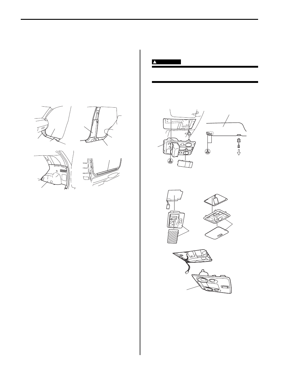
Head Lining Removal and Installation
S5JB0A9806002
WARNING
!
Refer to “Air Bag Warning: in Section 00”
before starting service work.
Removal
1) Remove overhead console (1) (if equipped) and
sunvisor (2).
2) Remove room lamp (2), luggage lamp (1) and spot
lamp (3) (if equipped).
1
2
1
3
4
5
I5JB0A980001-01
2
1
I5JB0A980002-02
2
1
3
I5JB0A980003-01
Interior Trim: 9H-2
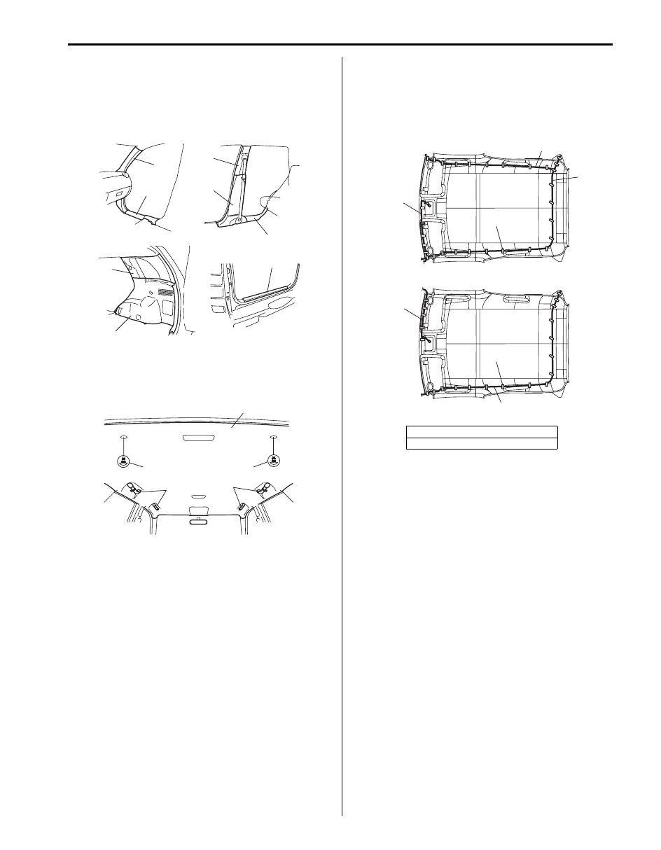
3) Remove front pillar upper trims (1), side sill scuffs (2)
(front and rear for 5 door model), center pillar inner
lower trims (3) (for 5 door model), center pillar inner
upper trims (4) (for 5 door model), back panel trim
(5), rear quarter lower trims (6) and rear quarter
upper trims (7).
4) Remove assistant grip (1).
5) Remove head lining clips (2) and remove head lining
(3).
Installation
Reverse removal procedure noting the following.
• Set roof harness (1), rear washer hose (2) and
antenna feeder (3) to head lining with adhesive tape
(4) as shown.
3 door model
1
2
2
4
5
3
6
7
I5JB0A980004-01
2
2
1
1
3
I5JB0A980005-01
[A]: Left-hand steering vehicle
[B]: Right-hand steering vehicle
1
2
3
4
1
2, 3
4
[A]
[B]
I5JB0A980006-02
Нет комментариевНе стесняйтесь поделиться с нами вашим ценным мнением.
Текст