Suzuki Grand Vitara JB416 / JB420. Manual — part 419
10C-6 Immobilizer Control System:
Diagnostic Trouble Code (DTC) Check
S5JB0AA304002
NOTE
To know how to use SUZUKI scan tool in
detail, refer to its operator’s manual.
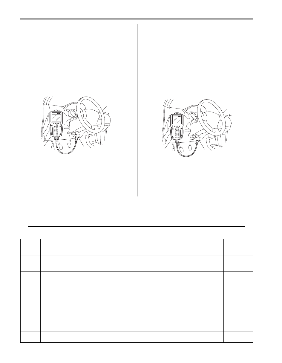
1) Turn the ignition switch to OFF position.
2) Connect SUZUKI scan tool to data link connector
(DLC) (1) located under instrument panel at driver’s
seat side.
Special tool
(A): SUZUKI scan tool
3) Turn the ignition switch to ON position.
4) Check if any DTC is stored in ECM according to the
instructions displayed on SUZUKI scan tool.
5) After completing the check, turn ignition switch to
OFF position, and then disconnect SUZUKI scan
tool from DLC.
Diagnostic Trouble Code (DTC) Clearance
S5JB0AA304003
NOTE
To know how to use SUZUKI scan tool in
detail, refer to its operator’s manual.
1) Turn the ignition switch to OFF position,
2) Connect SUZUKI scan tool to data link connector
(DLC) (1) located under instrument panel at driver’s
seat side.
Special tool
(A): SUZUKI scan tool
1) Turn the ignition switch to ON position.
2) Clear DTC(s) according to the instructions displayed
on SUZUKI scan tool.
3) After completing the clearance, turn the ignition
switch to OFF position, and then disconnect SUZUKI
scan tool from DLC.
Diagnostic Trouble Code (DTC) Table
S5JB0AA304004
ECM
NOTE
ECM detects diagnostic trouble code (DTC). Immobilizer control module (ICM) does not.
(A)
1
I4RS0BA30003-03
(A)
1
I4RS0BA30003-03
DTC No.
Detecting Item
Detecting Condition
Immobilizer
Indicator
Lamp
P1614 Transponder response error
Transponder code in the transponder built in
the ignition key cannot be read through
immobilizer control module (ICM).
Flash
P1615
Steering lock unit communication error (for
vehicle with keyless start system)
• While registering the transponder code in
the transponder built in the ignition key in
ECM, the keyless start control module sent
a signal to ECM indicating that the remote
controller ID code could not be registered.
• The remote controller ID code could not be
registered in the keyless start control
module or ECM. And, the registration
procedure of the transponder code in the
transponder built in the ignition key was
terminated forcibly.
Flash
P1616
Unregistered keyless start control module (for
vehicle with keyless start system)
ECM detects different ID codes registered in
ECM and keyless start system.
Flash

Immobilizer Control System: 10C-7
NOTE
If any DTC other than the above DTCs is detected, refer to “DTC Table in Section 1A”.
Scan Tool Data
S5JB0AA304005
The data listed below is the standard data obtained from the normal vehicle by using SUZUKI scan tool. Those are
output from ECM. Use them as reference.
Scan Tool Data Definitions
NUMBER OF LEARNT KEY
0 – 4 PCS: The number of the transponder code in the transponder built in the ignition key that is registered with ECM
NOTE
A maximum of four transponder codes can be registered with ECM. Therefore, the maximal value
should be 4.
INPUT YEAR
20**: The year in which the transponder code in the transponder built in the ignition key is registered with ECM
INPUT MONTH
1 – 12: The month in which the transponder code in the transponder built in the ignition key is registered with ECM
P1618
Keyless start control module CAN
communication error (for vehicle with keyless
start system)
Reception error of communication data for
keyless start control module is detected for
longer than specified time continuously.
Flash
P1621 Immobilizer communication line error
Communication error between immobilizer
control module (ICM) and ECM is detected by
ECM.
Flash
P1622 EEPROM read/write error
EEPROM in ECM is corrupted.
Flash
P1623 Unregistered transponder
Transponder code in the transponder built in
the ignition key is invalid.
Flash
P1625 Immobilizer antenna error
Immobilizer control module (ICM) is faulty.
Flash
P1636 Immobilizer information registration failure
Communication error between ECM and
BCM is detected by ECM.
No operation
P1638 Immobilizer information mismatched
• Communication error between ECM and
BCM is detected by ECM.
• Wrong ECM or BCM is used.
No operation
DTC No.
Detecting Item
Detecting Condition
Immobilizer
Indicator
Lamp
Scan Tool Data
Vehicle Condition
Normal Data
NUMBER OF LEARNT KEY
Ignition switch at ON position
0 – 4
INPUT YEAR
Ignition switch at ON position
2004 or later
INPUT MONTH
Ignition switch at ON position
1 – 12

10C-8 Immobilizer Control System:
Immobilizer Indicator Lamp Does Not Come ON with Ignition Switch ON and Engine Stop
S5JB0AA304012
Wiring Diagram
Refer to “Immobilizer Control System Wiring Circuit Diagram”.
Circuit Description
When the ignition switch is turned ON, ECM transmits the indication ON signal to the combination meter to turn ON the
immobilizer indicator lamp in case that there is not any problem with the immobilizer control system. Then, the
combination meter turns ON the lamp. When the engine is started up, ECM transmits the indication OFF signal to the
combination meter to turn OFF the lamp. Then, the combination meter turns OFF the immobilizer indicator lamp.
However, in case that there is some trouble with the immobilizer control system, the immobilizer indicator lamp flashes
ON and OFF when the ignition switch is turned ON.
Troubleshooting
Step
Action
Yes
No
1
Immobilizer indicator lamp power supply check
1) Turn the ignition switch to ON position.
Do other warning lights come ON?
Go to Step 2.
Go to Step 3.
2
Diagnostic Trouble Code (DTC) check
1) Check if DTC P1674, P1675, P1678 and/or P1685 are
detected by ECM referring to “Diagnostic Trouble Code
(DTC) Check”.
Is any of them detected?
Perform the
troubleshooting
referring to the
corresponding flowchart
in Section 1A.
Replace combination
meter with a known-
good one and recheck.
If the immobilizer
indicator lamp still
remains OFF, replace
ECM with a known-good
one and recheck.
3
Fuse check
1) Turn the ignition switch to OFF position.
2) Check if any related fuse is blown.
Is any fuse blown?
Replace blown fuse,
and then check for
short.
Go to Step 4.
4
Combination meter power supply wire circuit check
1) Remove combination meter referring to “Combination
Meter Removal and Installation in Section 9C”.
2) Check for proper connection at “G28-13” and “G28-15”
wire terminals of combination meter connector.
3) If OK, turn the ignition switch to ON position and
measure voltage between “G28-13” wire terminal of
combination meter and vehicle body ground.
Is it 10 – 14 V?
Go to Step 5.
Repair open in power
supply wire circuit.
5
Combination meter ground wire circuit check
1) Turn ignition switch OFF position.
2) Measure resistance between “G28-15” terminal of
combination meter connector and vehicle body ground.
Is resistance 1
Ω
or less?
Replace combination
meter with a know-good
one and recheck. If the
immobilizer indicator
lamp still remains OFF,
replace ECM with a
known-good one and
recheck.
Repair open or high
resistance in ground
wire circuit.

Immobilizer Control System: 10C-9
Immobilizer Indicator Lamp Remains ON after Engine Start
S5JB0AA304013
Wiring Diagram
Refer to “Immobilizer Control System Wiring Circuit Diagram”.
Circuit Description
When the ignition switch is turned ON, ECM transmits the indication ON signal to the combination meter to turn ON the
immobilizer indicator lamp in case that there is not any problem with the immobilizer control system. Then, the
combination meter turns ON the lamp. When the engine is started up, ECM transmits the indication OFF signal to the
combination meter to turn OFF the lamp. Then, the combination meter turns OFF the immobilizer indicator lamp.
However, in case that there is some trouble with the immobilizer control system, the immobilizer indicator lamp flashes
ON and OFF when the ignition switch is turned ON.
Troubleshooting
DTC P1614: Transponder Response Error
S5JB0AA304006
Detecting Condition and Trouble Area
Troubleshooting
Step
Action
Yes
No
1
Diagnostic Trouble Code (DTC) check
1) Start engine.
2) Check if any DTC is detected by ECM referring to
“Diagnostic Trouble Code (DTC) Check”.
Is any DTC detected?
Go to “Immobilizer
Control System Check”.
Go to Step 2.
2
CAN communication wire circuits check
1) Check CAN communication wire circuits between
combination meter and ECM referring to “DTC P1674:
CAN Communication (Bus Off Error) in Section 1A”.
Are wire circuits in good condition?
Replace combination
meter with a known-
good one and recheck.
If the immobilizer
indicator lamp remains
OFF, replace ECM with
a known-good one and
recheck.
Repair the malfunctional
wire circuit.
Detecting Condition
Trouble Area
Transponder code in the transponder built in the ignition
key cannot be read through immobilizer control module
(ICM).
• Use of the ignition key without the transponder
• Use of the unregistered ignition key
• Corruption of the transponder in the ignition key
• Immobilizer control module (ICM) faulty
• ECM faulty
Step
Action
Yes
No
1
Diagnostic Trouble Code (DTC) confirmation
1) Clear DTC(s) referring to “Diagnostic Trouble Code
2) Turn the ignition switch to OFF position.
3) Check if any DTC is detected referring to “Diagnostic
Is DTC P1614 still detected?
Go to Step 2.
The troubleshooting is
completed.
2
Diagnostic Trouble Code (DTC) check
1) Check if any DTC other than P1614 is detected referring
to “Diagnostic Trouble Code (DTC) Check”.
Is any DTC other than P1614 is detected?
Perform troubleshooting
referring to the
corresponding flowchart
in this section, and then
go to Step 3.
Go to Step 3.
Нет комментариевНе стесняйтесь поделиться с нами вашим ценным мнением.
Текст