Suzuki Grand Vitara JB416 / JB420. Manual — part 418
10C-2 Immobilizer Control System:
General Description
Immobilizer Control System Introduction
S5JB0AA301001
The immobilizer control system is an anti-theft device that immobilizes the vehicle. It stops the engine from working
and prevents the vehicle from being stolen. It mainly consists of the following components.
• Engine Control Module (ECM)
• Immobilizer control module (ICM) with the built-in coil antenna
• Ignition key with the built-in transponder
A code called the transponder code is memorized in the transponder. And, the code is registered with ECM. Basically,
when the ignition switch is turned ON, ECM reads the code by the coil antenna. Then, if the code in transponder in the
ignition key does not match with the one registered with ECM, ECM stops the operation of the fuel injection so as not
to start up the engine and turns the immobilizer indicator lamp ON and OFF using CAN communication lines. (In
addition to the above operation, ECM also turns the immobilizer indicator lamp ON and OFF when some trouble is
detected in the keyless start system.)
On-Board Diagnostic System Description (Self-diagnosis Function)
S5JB0AA301003
ECM diagnoses if there is any trouble with the immobilizer control system. The diagnostic information is stored as the
diagnostic trouble code (DTC) in ECM. To read the diagnostic information, use SUZUKI scan tool referring to
“Diagnostic Trouble Code (DTC) Check”.
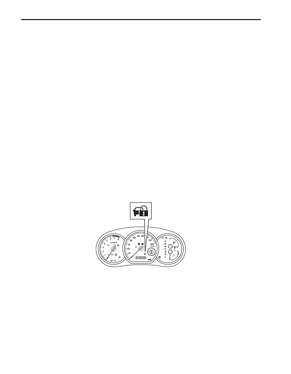
With the ignition switch turned ON (but the engine at stop) regardless of the condition of the engine and emission
control system, ECM indicates whether there is any trouble with the immobilizer control system or not by either lighting
ON or flashing ON and OFF the immobilizer indicator lamp.
Immobilizer indicator lamp lights ON:
No trouble exists in the immobilizer control system. (After starting up the engine, the lamp turns OFF.)
Immobilizer indicator lamp flashes ON and OFF:
There is some trouble in the immobilizer control system or in the keyless start system. Its diagnostic information is
stored in ECM.
I5JB0AA30002-01
Immobilizer Control System: 10C-3
Schematic and Routing Diagram
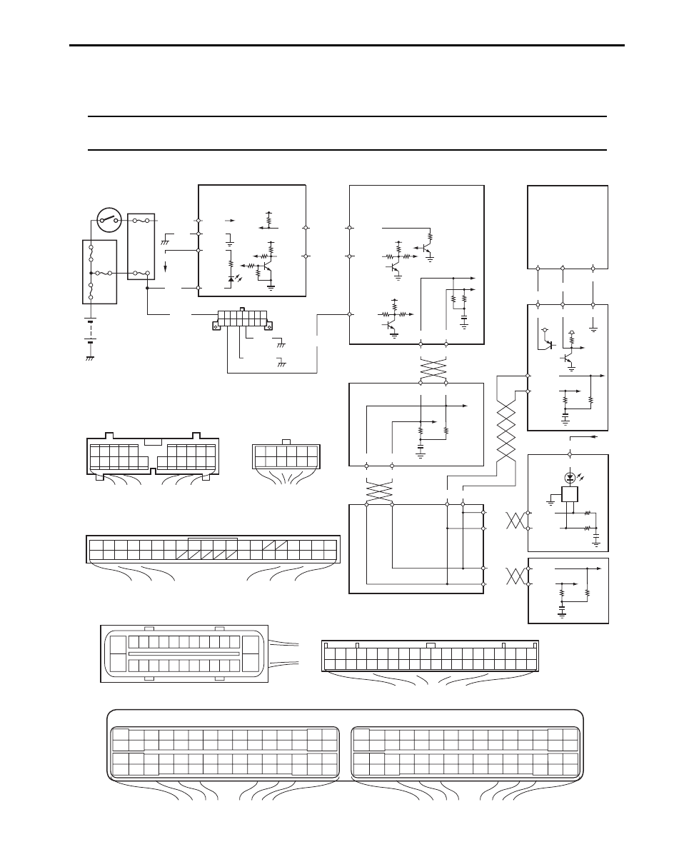
Immobilizer Control System Wiring Circuit Diagram
S5JB0AA302001
NOTE
For more details about power supply and ground wire circuits for ECM, BCM, ABS, keyless start
control module and combination meter, refer to “System Circuit Diagram in Section 9A”.
BLK/WHT
BLK
WHT/BLU
WHT/RED
12V
G24-1
G24-2
12V
5V
12V
12V
PNK/BLU
GRY/BLU
G24-4
G24-3
E23-13
E23-28
BLK
BLK/YEL
12V
E23-5
WHT
PPL/WHT
E03-8 E03-10
E23-4 E23-19
WHT
RED
E03-12 E03-6
RED
WHT
RED
WHT
RED
WHT
G31-1
G31-3
G28-8
G28-10
G42-19
G42-18
G42-20 G42-29 G42-30
5V
ORN
BRN/YEL
BLK/YEL
G22-3 G22-7 G22-8
G28-13
PPL/RED
E23
C37
3
4
18
19
5
6
7
10
11
17
20
47
46
49
50
51
21
22
52
16
25
9
24
14
29
55
57
54 53
59
60
58
2
26
27
28
15
30
56
48
32
31
34
35
36
37
40
42
39 38
44
45
43
41
33
1
12
13
23
8
3
4
18
19
5
6
7
10
11
17
20
47
46
49
50
51
21
22
52
16
25
9
24
14
29
55
57
54 53
59
60
58
2
26
27
28
15
30
56
48
32
31
34
35
36
37
40
42
39 38
44
45
43
41
33
1
12
13
23
8
1
2
3
4
5
6
7
8
9
10
11
17
16 15 14 13 12
22 21 20 19 18
G28
G31
1
2
3
4
7
8
9
10
11
14
15
16
36
34
35
24 23
21
22
28 27
25
26
37
39 38
40
18 17
13 12
19
20
1
2
3
4
G24
1
2
3
4
5
6
7
8
9
10
11
12
13
14
15
16
17
18
19
20
21
22
23
24
25
26
27
28
29
30
31
32
33
34
35
36
37
38
39
40
G44
E03
1
2
3
4
5
6
7
8
9
10
11
12
13
14
15
16
17
18
19
20
21
22
23
24
25
26
1
2
2
2
2
2
3
4
2
5
6
7
8
9
10
11
12
13
14
15
16
17
18
19
20
BLK
BLK/RED
G24-5
G24-6
5
6
14
I5JB0AA30003-02
10C-4 Immobilizer Control System:
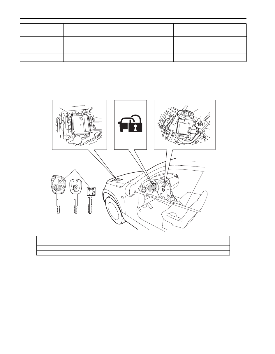
Component Location
Immobilizer Control System Components Location
S5JB0AA303001
1. Battery
6. Data link connector (DLC)
11. Keyless start control module
16. Immobilizer control module (ICM) connector
(harness side view)
2. Fuse
7. ECM
12. Combination meter
17. BCM connector (harness side view)
3. Ignition switch
8. ABS control module
13. From fuse
18. ABS control module connector (harness side
view)
4. Junction block assembly
9. Junction connector
14. BCM
19. Keyless start control module connector
(harness side view)
5. Immobilizer control
module (ICM)
10. Steering lock unit
15. Combination meter connector (harness
side view)
20. ECM connectors (harness side view)
1
2
3
4
5
6
7
I5JB0AA30001-01
1. ECM
5. Ignition key without keyless entry system
2. Immobilizer indicator lamp
6. Ignition key with keyless start system
3. Immobilizer control module (ICM)
7. Transponder
4. Ignition key with keyless entry system
Immobilizer Control System: 10C-5
Diagnostic Information and Procedures
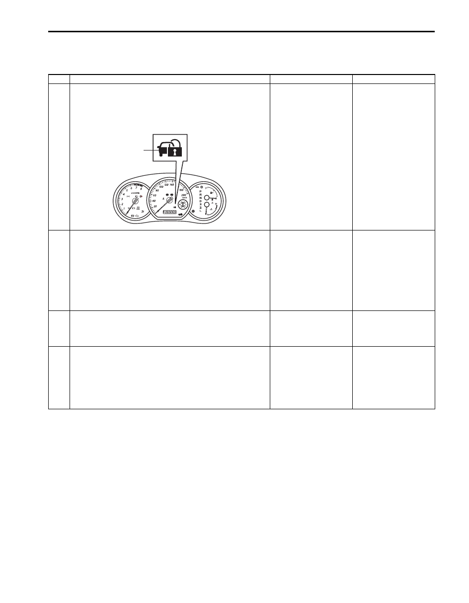
Immobilizer Control System Check
S5JB0AA304001
Step
Action
Yes
No
1
Immobilizer indicator lamp ON check
1) Turn ignition switch to ON position using ignition key.
Does immobilizer indicator lamp (1) come on?
Go to Step 2.
Check if DTC P1636
and/or P1638 are
detected by ECM
referring to “Diagnostic
Trouble Code (DTC)
Check”. If detected,
perform the
troubleshooting
referring to the
corresponding flowchart
in this section. If not
detected, go to
“Immobilizer Indicator
Lamp Does Not Come
ON with Ignition Switch
ON and Engine Stop”.
2
Immobilizer indicator lamp flash check
Does immobilizer indicator lamp flash on and off
continuously in Step 1?
Check what DTC is
detected by ECM
referring to “Diagnostic
Trouble Code (DTC)
Check”. Then, perform
the troubleshooting
referring to the
corresponding flowchart
in this section.
Go to Step 3.
3
Engine start check
1) Start engine using ignition key.
Does engine start?
Go to Step 4.
Perform “Engine and
Emission Control
System Check in
Section 1A”.
4
Immobilizer indicator lamp remain ON check
1) Check if immobilizer indicator lamp remains ON after
engine start.
Does immobilizer indicator lamp remain ON after engine
start?
Go to “Immobilizer
Indicator Lamp
Remains ON after
Engine Start”.
Immobilizer control
system is in good
condition. Then, go to
“Keyless Start System
Check in Section 10E”
for the vehicle with
keyless start system.
1
I5JB0AA30004-01
Нет комментариевНе стесняйтесь поделиться с нами вашим ценным мнением.
Текст