Suzuki Grand Vitara JB416 / JB420. Manual — part 267
6C-2 Power Assisted Steering System:
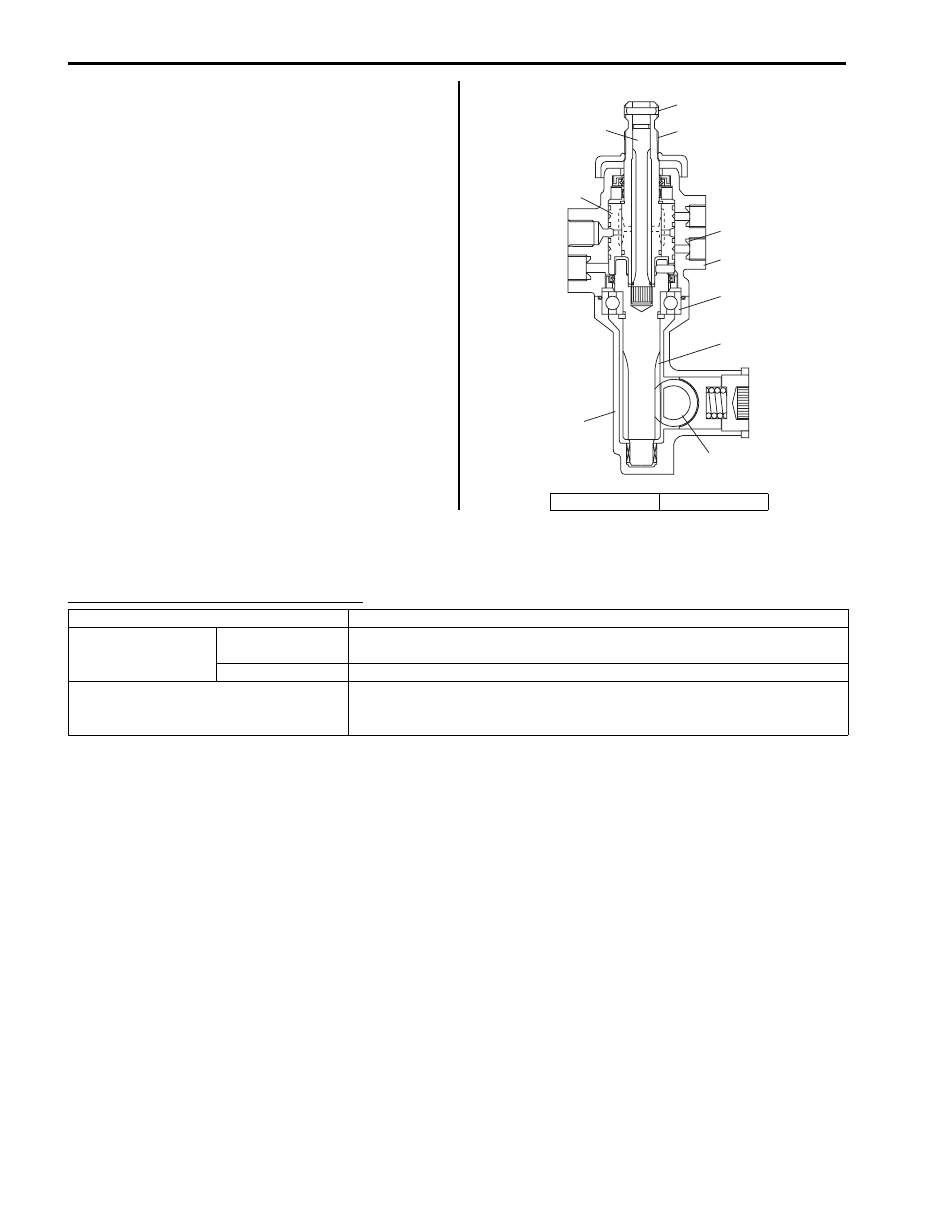
Steering Gear Case Construction
S5JB0A6301002
The steering gear case consists of two sections: one
including a cylinder and the other a valve. Main
components of the cylinder section are a gear case (7), a
rack (8) and a tube and those of the valve section are a
valve case (10), a sleeve (4) and a stub shaft (2). The
sleeve is linked with the pinion (6) through a pin (1) and
the valve and stub shaft are integrated into one unit.
Then the pinion and the stub shaft are linked to each
other by means of the torsion bar (3).
Thus, when the stub shaft moves, the valve changes its
position, thereby switching the hydraulic passage from
the pump to the cylinder to help steering operation.
When turning the steering wheel feels heavy due to P/S
fluid leakage or for some other reason (i.e., when in the
manual steering mode), the stub shaft and pinion are in
direct linkage and the force is output directly through the
pinion and rack.
P/S Pump Construction
S5JB0A6301003
The power steering pump is a vane type and is driven by the V-ribbed belt from the crankshaft.
Power steering (P/S) pump specifications
Flow Control Valve (Relief Valve)
As the discharge rate of the P/S pump increases in proportion to the pump revolution speed, a flow control valve is
added to control it so that the optimum amount of fluid for steering operation is supplied according to the engine speed
(driving condition).
5. Bearing
9. Ferrule
1
3
2
4
9
5
6
7
10
8
I5JB0A630002-01
Model
Vane type
Hydraulic pressure
control
Relieved
pressure
6370 kPa (63.7 kg/cm
2
, 906 psi) for M16 engine
6860 kPa (68.6 kg/cm
2
, 975 psi) for J20 engine
Control device
Flow control valve and relief valve
Power steering pressure switch
Switch turns on (closes) when the pressure is higher than 2500 –
3000 kPa (25 – 30 kg/cm
2
, 356 – 427 psi).
ECM uses this signal for idle speed control.

Power Assisted Steering System: 6C-3
Schematic and Routing Diagram
P/S Fluid Flow Diagram
S5JB0A6302001
Diagnostic Information and Procedures
P/S System Symptom Diagnosis
S5JB0A6304001
IYSQ01630002-01
1. Power steering pump
3. P/S fluid reservoir
5. Pinion
2. Valve section
4. Rack
6. Cylinder
Condition
Possible cause
Correction / Reference Item
Steering wheel feels
heavy (at low speed)
Fluid deteriorated, low viscosity,
different type of fluid mixed
Replace fluid.
Pipes or hoses deformed, air entering
through joint
Replace defective part.
Insufficient air purging from P/S circuit
Purge air.
P/S belt worn, lacking in tension
Adjust belt tension or replace belt as
necessary.
Tire inflation pressure excessively low
Inflate tire.
Front end alignment out of order
Check and adjust front end alignment.
Steering wheel installed improperly
(twisted)
Install steering wheel correctly.
Bind in tie-rod or tie-rod end ball joint
Replace defective part.
P/S pump hydraulic pressure fails to
increase
Check pressure and repair or replace defective
part.
P/S pump hydraulic pressure increases
but slowly
Check pressure and repair or replace defective
part.
Steering gear case malfunction
Replace gear case.
Steering wheel feels
heavy momentarily when
turning it to the left or
right
Air drawn in due to insufficient amount of
fluid
Add fluid and purge air.
Slipping P/S belt
Adjust belt tension or replace belt as
necessary.
P/S pump hydraulic pressure fails to
increase
Check pressure and repair or replace defective
part.
P/S pump hydraulic pressure increases
but slowly
Check pressure and repair or replace defective
part.
Steering gear case malfunction
Replace gear case.

6C-4 Power Assisted Steering System:
Steering Wheel Check
S5JB0A6304002
• Check steering wheel for looseness or rattle by trying
to move it in its shaft direction and lateral direction.
If found defective, repair or replace.
• Check steering wheel for play, holding car in straight
forward condition on the ground and with engine
stopped.
Steering wheel play “a”
: 0 – 30 mm (0 – 1.2 in.)
If steering wheel play is not within specification,
inspect as follows and replace if found defective.
– Tie-rod end ball stud for wear
– Lower ball joint for wear
– Steering shaft joint for wear
– Steering pinion or rack gear for wear or breakage
– Each part for looseness
Poor recovery from turns Deformed pipes or hoses
Replace defective part.
Steering column installed improperly
Install steering column correctly.
Front end alignment out of order
Check and adjust front end alignment.
Ball joints binding
Replace defective part.
P/S pump hydraulic pressure fails to
increase
Check pressure and repair or replace defective
part.
P/S pump hydraulic pressure increases
but slowly
Check pressure and repair or replace defective
part.
Steering gear case malfunction
Replace gear case.
Vehicle pulls to one side
during straight driving
Mismatched or uneven tire
Replace tire.
Low or uneven tire inflation pressure
Inflate tires to proper pressure or adjust right
and left tires inflation pressure.
Brake dragging in one wheel
Repair.
Front end alignment out of order
Check and adjust front end alignment.
Rear end alignment out of order
Check and adjust rear end alignment.
Malfunction of control valve in gear case Replace gear case.
Steering wheel play is
large and vehicle wanders
Refer to “Steering Symptom Diagnosis
in Section 6A”.
Fluid leakage
Loose joints of (hydraulic pressure)
pipes and hoses
Retighten.
Deformed or damaged pipes or hoses
Replace defective part.
Abnormal noise
Air drawn in due to insufficient amount of
fluid
Add fluid and purge air.
Air mixed into fluid from pipes or hoses Replace pipes or hoses.
Slipping (loose) P/S belt
Adjust belt tension.
Worn P/S belt
Replace belt.
Loose gear case fastening bolt
Retighten bolts.
Loose linkage or joints
Retighten.
Pipes or hoses in contact with part of
vehicle body
Install pipes and hoses correctly.
Vanes of P/S pump defective
Replace defective part.
Malfunction of control valve in gear case Replace gear case.
Bearing of P/S pump shaft defective
Replace bearing.
No idle up
Power steering pressure switch
defective
Replace power steering pressure switch.
Condition
Possible cause
Correction / Reference Item
I5JB0A630004-02
Power Assisted Steering System: 6C-5
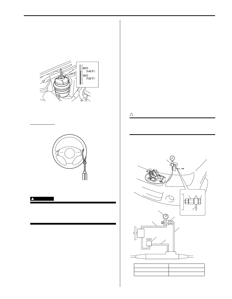
Steering Force Check
S5JB0A6304003
1) Place vehicle on level road and set steering wheel at
straight-ahead position.
2) Check that tire inflation pressure is as specified.
(Refer to tire placard.)
3) Start engine and keep it running till power steering
fluid is warmed to 50 to 60
°C (122 to 140 °F).
4) With engine idling, measure steering force by pulling
spring balancer hooked on steering wheel in
tangential direction.
Steering force
: Less than 30 N (3.0 kg, 6.6 lb)
Steering Wheel Recovery Check
S5JB0A6304006
WARNING
!
When performing a check, select a place
where there is no traffic or possibility of a
traffic accident and be very careful during
testing to avoid occurrence of an accident.
Check steering wheel for recovery as follows.
1) Rotate it to either right or left end.
2) Keep it at the end, and start the vehicle slowly.
3) Accelerate vehicle slowly.
If steering wheel begins to return at the vehicle speed
less than 10 km/h (6.3 mph), it is normal condition.
If the check result is abnormal, diagnose the fault part
referring to “Poor recovery from turns” in “P/S System
Symptom Diagnosis”.
Idle Up System Check
S5JB0A6304004
1) Warm up engine to normal operating temperature.
2) Turn A/C switch OFF, if equipped.
3) Turn steering wheel fully and check idle speed.
Engine idle speed drops a little momentarily when
steering wheel is turned fully but returns to its
specified level immediately.
If power steering pressure switch connector is
connected, check the same with that connector
disconnected.
Momentary drop of engine idle speed should be less
when it is connected than when disconnected.
Hydraulic Pressure in P/S Circuit Check
S5JB0A6304005
1) After cleaning joint of high pressure hose and P/S
pump thoroughly, disconnect hose from pump and
install special tool (oil pressure gauge, attachment
and hose).
CAUTION
!
Take care not to cause damage to A/C
condenser during service operation, if
equipped.
Special tool
(A): 09915–77412
(B): 09915–77420
I5JB0A630005-01
I5JB0A630057-01
1. P/S fluid reservoir
4. Union bolt
2. Attachment
5. High pressure side
3. Gasket
6. Low pressure side
(A)
(A)
(B)
(B)
5
1
6
(B)
2
5
4
3
I5JB0A630007-02
Нет комментариевНе стесняйтесь поделиться с нами вашим ценным мнением.
Текст