Suzuki Grand Vitara JB416 / JB420. Manual — part 110
1D-108 Engine Mechanical: For J20 Engine
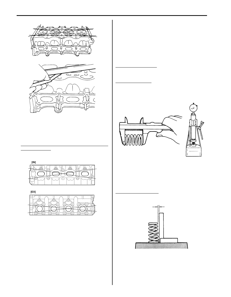
• Distortion of manifold seating faces:
Check seating faces of cylinder head for manifolds,
using a straightedge and thickness gauge, in order to
determine whether these faces should be corrected or
cylinder head replaced.
Distortion for cylinder head surface on intake and
exhaust manifold
Limit: 0.05 mm (0.002 in.)
Valve Spring Inspection
S5JB0A1426048
Valve Spring Free Length and Preload
Referring to data, check to be sure that each spring is in
sound condition, free of any evidence of breakage or
weakening. Remember, weakened valve springs can
cause chatter, not to mention possibility of reducing
power output due to gas leakage caused by decreased
seating pressure.
Valve spring free length
Standard: 51.13 mm (2.013 in.)
Limit: 50.13 mm (1.974 in.)
Valve spring preload
Standard: 219 – 241 N (21.9 – 24.1 kg) for 37.60 mm
(48.3 – 53.1 lb/1.480 in.)
Limit: 208 N (20.8 kg) for 37.60 mm (45.9 lb/1.480 in.)
Spring Squareness
Use a square and surface plate to check each spring for
squareness in terms of clearance between end of valve
spring and square. Valve springs found to exhibit a
larger clearance than limit must be replaced.
Valve spring squareness
Limit: 1.6 mm (0.063 in.)
I2RH0B140106-01
I2RH0B140107-01
I2RH01140143-01
I2RH01140144-01
Engine Mechanical: For J20 Engine 1D-109
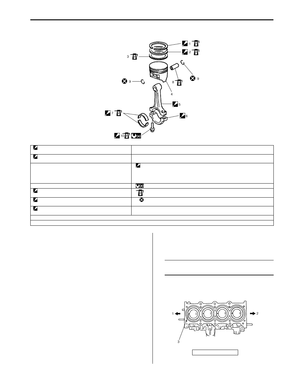
Pistons, Piston Rings, Connecting Rods and Cylinders Components
S5JB0A1426036
Pistons, Piston Rings, Connecting Rods and
Cylinders Removal and Installation
S5JB0A1426037
Removal
1) Remove engine assembly from vehicle referring to
“Engine Assembly Removal and Installation: For J20
Engine”.
2) Remove oil pump with oil pump strainer. Refer to “Oil
Pump Removal and Installation: For J20 Engine in
Section 1E” for removal.
3) Remove cylinder head. Refer to “Valves and
Cylinder Head Removal and Installation: For J20
Engine” for removal.
4) Mark cylinder number on all pistons, connecting rods
and connecting rod caps.
5) Remove connecting rod bearing caps.
6) Clean carbon from top of cylinder bore before
removing piston from cylinder.
7) Push piston and connecting rod assembly out
through the top of cylinder bore.
Installation
1) Apply engine oil to pistons, rings, cylinder walls,
connecting rod bearings and crank pins.
NOTE
Do not apply oil between connecting rod and
bearing or between bearing cap and bearing.
2) When installing piston and connecting rod assembly
into cylinder bore, point front mark (3) on piston head
to crankshaft pulley side (1).
1. Top ring
: “TOP” mark provided on piston ring comes to facing up.
8. Piston pin
2. 2nd ring
: “TOP” mark provided on piston ring comes to facing up.
9. Piston pin circlip
3. Oil ring
10. Connecting rod bolt
: Check connecting rod bolt, plastic deformation tightening bolt, for deformation when
reuse it due to plastic deformation tightening referring to “Connecting Rod Bolt” under
“Pistons, Piston Rings, Connecting Rods and Cylinders Inspection and Cleaning: For
J20 Engine” if it is reused.
4. Piston
: 15 N
⋅m (1.5 kgf-m, 11.0 lb-ft) 45° and 45° by the specified procedure.
5. Connecting rod
: Apply engine oil to sliding surface of each part.
6. Connecting rod bearing cap
: See “A”
: Do not reuse.
7. Connecting rod bearing
: See “B”
“A”: Point arrow mark on cap to crankshaft pulley side. Do not apply engine oil to inner surface of bearing cap.
“B”: Do not apply engine oil between con-rod big end and bearing, between cap and bearing.
I5JB0A142048-02
2. Flywheel side
I5JB0A142049-01
1D-110 Engine Mechanical: For J20 Engine
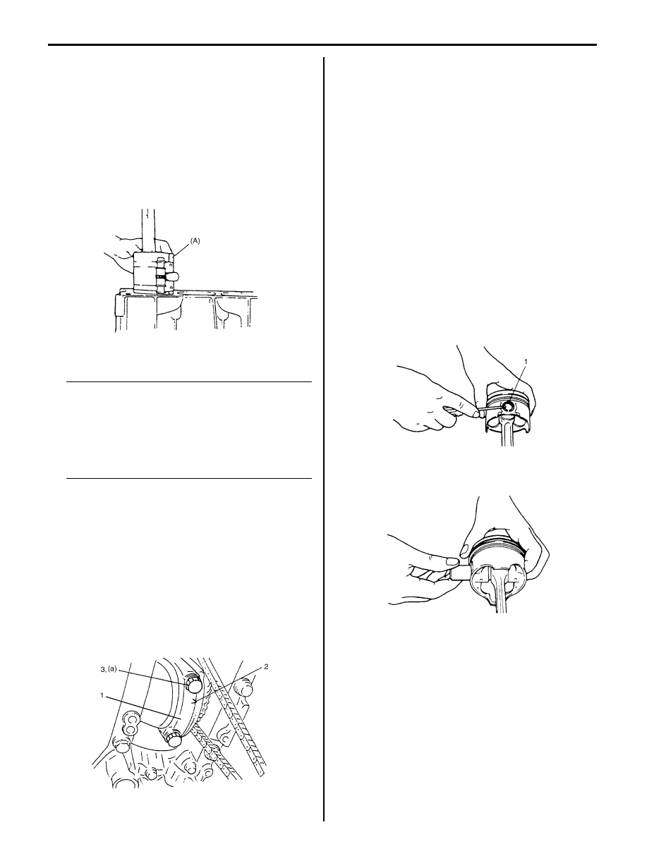
3) Install piston and connecting rod assembly into
cylinder bore. Use special tool (Piston ring
compressor) to compress rings. Guide connecting
rod into place on crankshaft.
Using a hammer handle, tap piston head to install
piston into bore. Hold ring compressor firmly against
cylinder block until all piston rings have entered
cylinder bore.
Special tool
(A): 09916–77310
4) Install connecting rod bearing cap (1) as follows.
NOTE
If connecting rod bolt is reused, make sure to
check connecting rod bolt for deformation
referring to “Connecting Rod Bolt
Deformation (Plastic Deformation Tightening
Bolt)” under “Pistons, Piston Rings,
Connecting Rods and Cylinders Inspection
and Cleaning: For J20 Engine”.
a) Point arrow mark (2) on cap to crankshaft pulley
side.
b) Apply engine oil to new connecting rod bolts (3).
c) Tighten all connecting rod bolts to 15 N
⋅m (1.5
kgf-m, 11.0 lb-ft).
d) Retighten them by turning through 45
°.
e) Repeat step d) once again.
Tightening torque
Connecting rod bolt (a): Tighten 15 N
⋅m (1.5
kgf-m, 11.0 lb-ft), 45
° and 45° by the specified
procedure.
5) Install cylinder head. Refer to “Valves and Cylinder
Head Removal and Installation: For J20 Engine” for
installation.
6) Install oil pan. Refer to “Oil Pan and Oil Pump
Strainer Removal and Installation: For J20 Engine in
Section 1E” for installation.
7) Install engine assembly to vehicle referring to
“Engine Assembly Removal and Installation: For J20
Engine”.
Pistons, Piston Rings, Connecting Rods and
Cylinders Disassembly and Assembly
S5JB0A1426038
Disassembly
1) Using piston ring expander, remove two
compression rings (Top and 2nd) and oil ring from
piston.
2) Remove piston pin from connecting rod.
• Ease out piston pin circlips (1), as shown.
• Force piston pin out.
I2RH01140149-01
I4RH01140037-01
I2RH01140151-01
I2RH01140152-01
Engine Mechanical: For J20 Engine 1D-111
Assembly
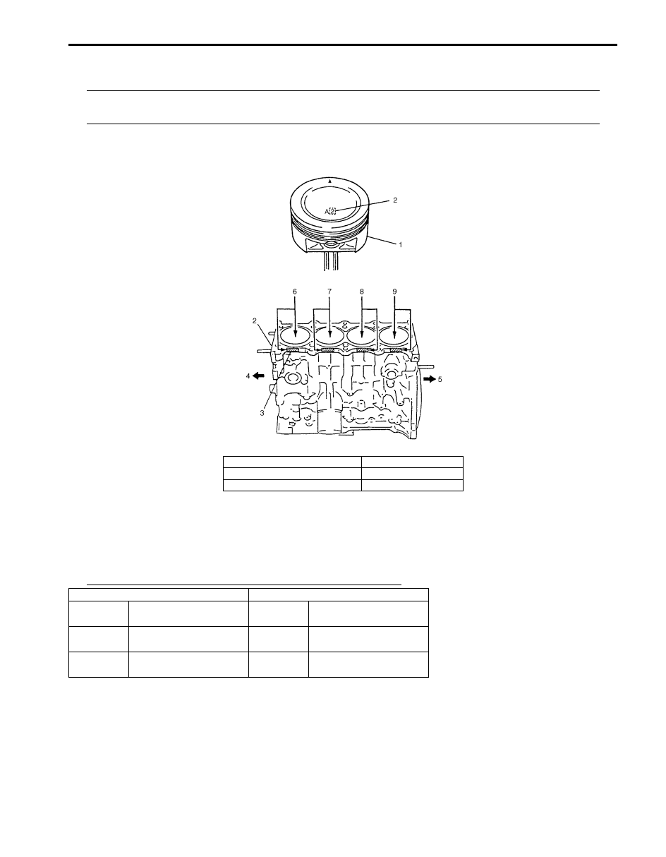
NOTE
Two sizes of piston are available as standard size spare part so as to ensure proper piston-to-cylinder
clearance. When installing a standard size piston, make sure to match piston with cylinder as follows.
1) Each piston (1) has stamped number (2) as shown. It represents outer diameter of piston.
2) There are also painted color (3) of red or blue on cylinder block (2) as shown.
3) Stamped number on piston and painted color (or stamped number) on cylinder block should correspond. That is,
install number “2” stamped piston to cylinder which is identified with blue painted (or “2” stamped) and a number
“1” piston to cylinder with red painted (or “1” stamped).
Also, a letter “A” or “B” is stamped on piston head but ordinarily it is not necessary to discriminate each piston by
this letter.
Piston outer diameter and cylinder bore diameter specification
4. Crank shaft pulley side
7. No.2 cylinder
5. Flywheel side
8. No.3 cylinder
6. No.1 cylinder
9. No.4 cylinder
Piston
Cylinder
Number
Outer diameter
Paint
(Number)
Bore diameter
1
83.9800 – 83.9900 mm
(3.3063 – 3.3066 in.)
Red (1)
84.0101 – 84.0200 mm
(3.3075 – 3.3078 in.)
2
83.9700 – 83.9799 mm
(3.3059 – 3.3062 in.)
Blue (2)
84.0000 – 84.0100 mm
(3.3071 – 3.3074 in.)
I5JB0A142050-01
Нет комментариевНе стесняйтесь поделиться с нами вашим ценным мнением.
Текст